
Semiconductor device and method of fabricating the same

a semiconductor device and semiconductor technology, applied in the field of three-dimensional semiconductor devices, can solve the problems of significant manufacturing obstacles in achieving low-cost, increasing the integration density of such devices, and increasing the cost of process equipmen

Active Publication Date: 2016-02-18
SAMSUNG ELECTRONICS CO LTD
View PDF6 Cites 88 Cited by
  • Summary
  • Abstract
  • Description
  • Claims
  • Application Information

AI Technical Summary

Benefits of technology

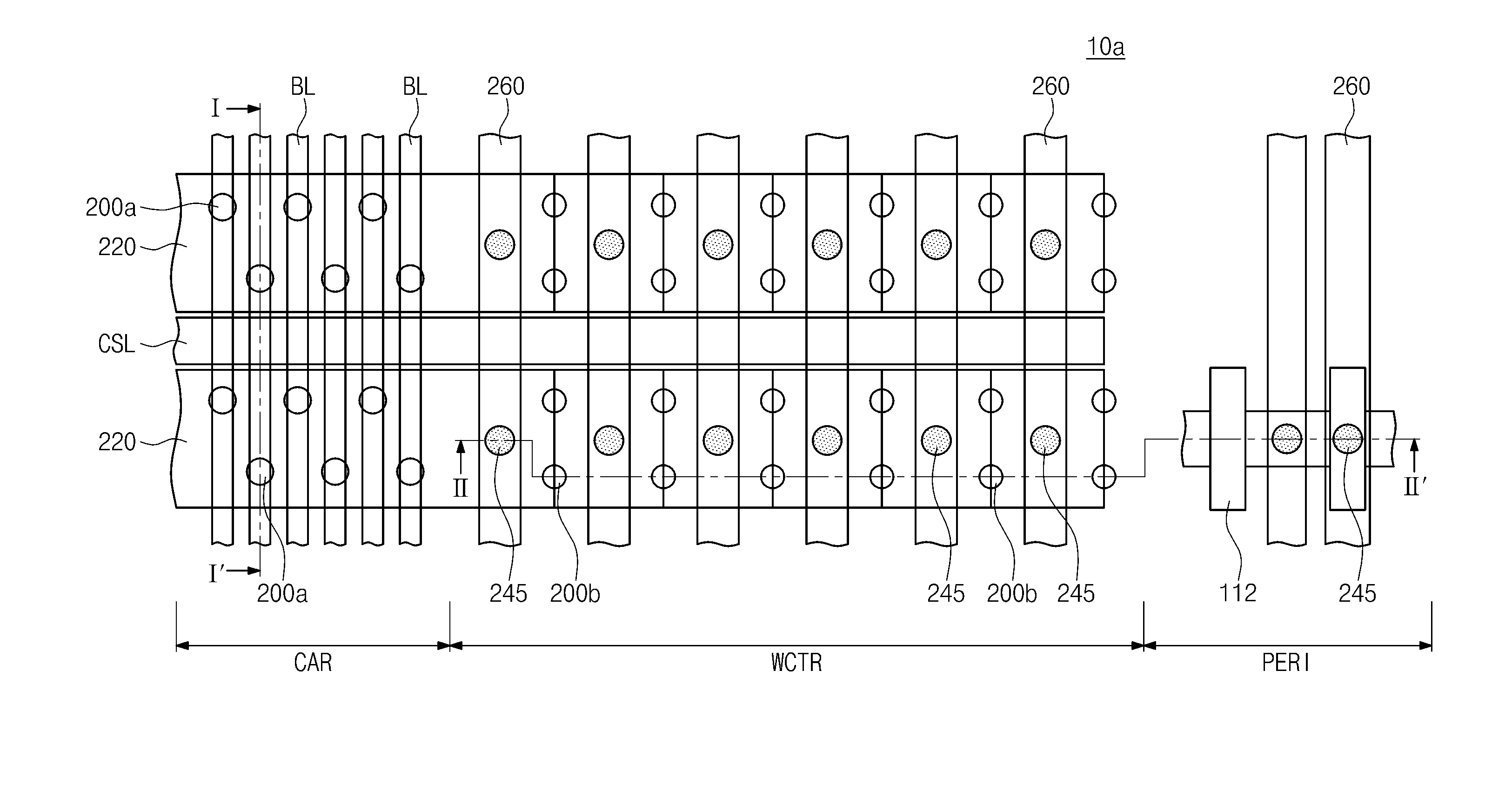
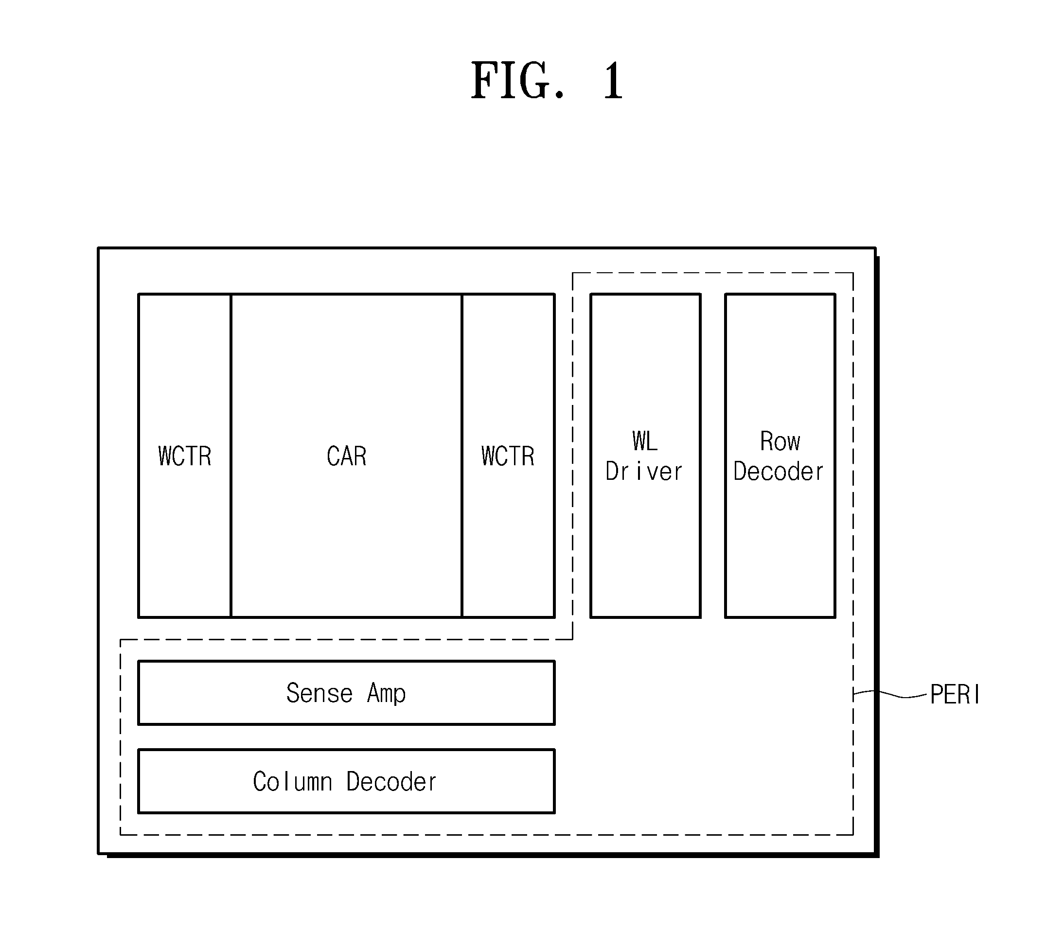
The patent text describes a three-dimensional semiconductor device and a method of fabricating it. The device includes a substrate with a cell array region, a word line contact region, and a peripheral circuit region. Gate electrodes are stacked on the substrate and extend from the cell array region to the word line contact region. A channel hole penetrates the gate electrodes on the cell array region and exposs an active region of the substrate. A dummy hole penetrates the gate electrodes on the word line contact region and exposs a device isolation layer provided on the substrate. A semiconductor pattern and a vertical channel structure are provided in the channel hole. A dummy pillar is provided in the dummy hole. The invention increases the integration density of the semiconductor device and provides a more efficient method of fabrication.

Problems solved by technology

Further integration of such devices is becoming more difficult (and costly) as patterning technologies approach practical limits.
At the very least, prohibitively expensive process equipment would be needed to achieve major advances in 2D memory cell array device integration.
However, there are significant manufacturing obstacles in achieving low-cost, mass-production of 3D semiconductor devices, particularly in the mass-fabrication of 3D devices that maintain or exceed the operational reliability of their 2D counterparts.

Method used


Image

  • Semiconductor device and method of fabricating the same
  • Semiconductor device and method of fabricating the same
  • Semiconductor device and method of fabricating the same

Examples


Embodiment Construction

[0036]Example embodiments of the inventive concepts will now be described more fully with reference to the accompanying drawings, in which example embodiments are shown. Example embodiments of the inventive concepts may, however, be embodied in many different forms and should not be construed as being limited to the embodiments set forth herein; rather, these embodiments are provided so that this disclosure will be thorough and complete, and will fully convey the concepts of example embodiments to those of ordinary skill in the art. In the drawings, the thicknesses of layers and regions are exaggerated for clarity. Like reference numerals in the drawings denote like elements, and thus their description will be omitted.

[0037]It will be understood that when an element is referred to as being “connected” or “coupled” to another element, it can be directly connected or coupled to the other element or intervening elements may be present. In contrast, when an element is referred to as bei...


PUM


Abstract

A three-dimensional semiconductor device may include a substrate including a cell array region, a word line contact region, and a peripheral circuit region, gate electrodes stacked on the substrate to extend from the cell array region to the word line contact region, a channel hole penetrating the gate electrodes on the cell array region and exposing an active region of the substrate, a dummy hole penetrating the gate electrodes on the word line contact region and exposing a device isolation layer provided on the substrate, and a semiconductor pattern provided in the channel hole but not in the dummy hole.

Description

CROSS-REFERENCE TO RELATED APPLICATIONS[0001]This U.S. non-provisional patent application claims priority under 35 U.S.C. §119 to Korean Patent Application No. 10-2014-0104417, filed on Aug. 12, 2014, in the Korean Intellectual Property Office, the entire contents of which are hereby incorporated by reference.BACKGROUND OF THE INVENTION[0002]Example embodiments of the inventive concepts relate to a semiconductor device and a method of fabricating the same, and in particular, to a three-dimensional semiconductor device and a method of fabricating the same.[0003]The continued development of highly integrated semiconductor devices is spurred in part by consumer demand for low-cost, superior performance products. Indeed, particularly in the case of semiconductor devices, increased device integration is a major factor in achieving price points satisfying market demands. Conventionally, semiconductor memory devices include planar or two-dimensional (2D) memory cell arrays, i.e., memory ce...

Claims


Application Information

Patent Timeline
Patent Type & Authority Applications(United States)
IPC IPC(8): H10B69/00
CPCH01L27/11573H01L27/11582H10B43/10H10B43/50H10B43/40H10B43/35H10B43/27H10B51/20
Inventor YOO, DONGCHULKIM, CHAEHOAHN, JAEYOUNGLEE, WOONG
Owner SAMSUNG ELECTRONICS CO LTD
Learn More