Fast start-up circuit of a flyback power supply and method thereof
- Summary
- Abstract
- Description
- Claims
- Application Information
AI Technical Summary
Benefits of technology
Problems solved by technology
Method used
Image
Examples
first embodiment
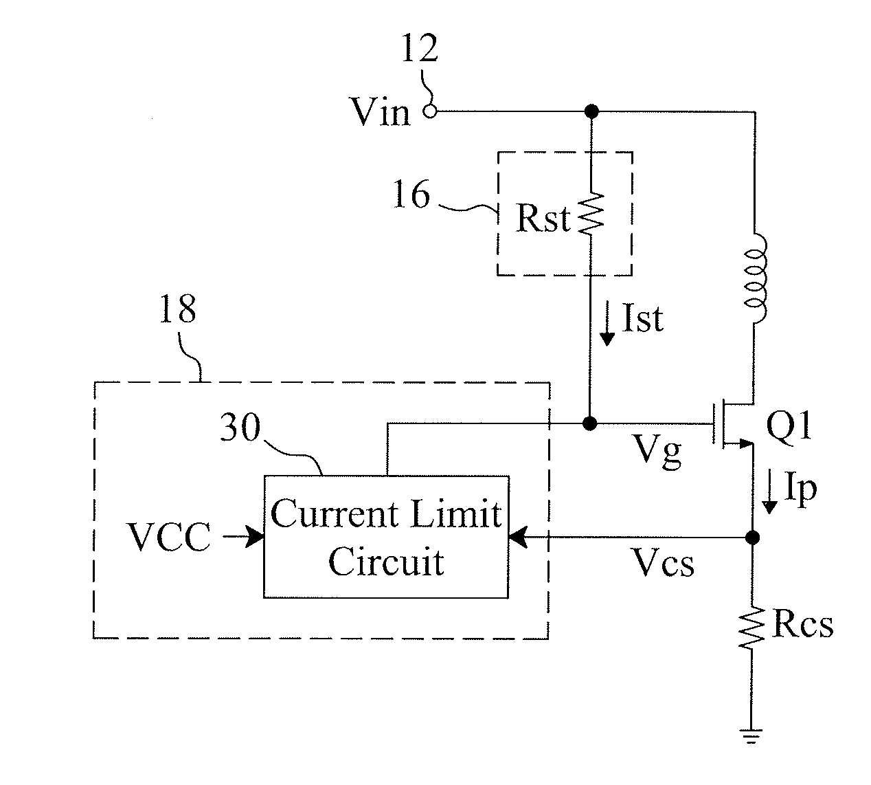
[0020]FIG. 6 shows the current limit circuit 30 in FIG. 5. The current limit circuit 30 comprises a first switch SW1, a low dropout 24, a comparator 28, and a threshold generator 32. The low dropout 24 provides a voltage for serving as a power of the comparator 28. The threshold generator 32 provides a current limit threshold Vth_cs that is controlled by the supply voltage VCC. The comparator 28 compares the first sensing signal Vcs with the current limit threshold Vth_cs. When the first sensing signal Vcs reaches the current limit threshold Vth_cs, the comparator 28 turns on the first switch SW1, so that the control terminal of the power switch Q1 is connected to a ground, thereby turning off the power switch Q1 for determining the maximum of the current Ip. The threshold generator 32 includes a threshold value resistor Rth, a second switch SW2, and an bias generator 34. Wherein, the threshold value resistor Rth generates the current limit threshold Vth_cs according to the current ...
second embodiment
[0022]FIG. 8 shows the current limit circuit 30 in FIG. 5. The current limit circuit 30 includes the first switch SW1, the low dropout 24, the comparator 28, and a voltage divider circuit 37. In this embodiment, the low dropout 24 provides the voltage for serving as the power of the comparator 28. The voltage divider circuit 37 divides the first sensing signal Vcs to generate a second sensing signal Vcs_d. A voltage dividing ratio of the voltage divider circuit 37 is controlled by the supply voltage VCC. The comparator 28 compares the second sensing signal Vcs_d with the current limit threshold Vth_cs. When the second sensing signal Vcs_d reaches the current limit threshold Vth_cs, the comparator 28 turns on the first switch SW1, so that the control terminal of the power switch Q1 is connected to the ground, thereby turning off the power switch Q1 for determining the maximum of the current Ip. In this embodiment, the current limit threshold Vth_cs is a preset fixed value. The voltag...
third embodiment
[0024]FIG. 9 shows the current limit circuit 30 in FIG. 5. The current limit circuit 30 includes the first switch SW1, the low dropout 24, the comparator 28, and an offset control circuit 46. In this embodiment, the low dropout 24 provides the voltage for serving as the power of the comparator 28. The offset control circuit 46 determines an offset voltage Voffset (not shown) according to the supply voltage VCC so as to offsets the first sensing signal Vcs and generates the second sensing signal Vcs_ofs. The offset voltage Voffset rises in accordance with the ascension of the supply voltage VCC. The comparator 28 compares the second sensing signal Vcs_ofs with the current limit threshold Vth_cs. The current limit threshold Vth_cs is a preset fixed value. When the second sensing signal Vcs_ofs reaches the current limit threshold Vth_cs, the comparator 28 turns on the first switch SW1 and connects the control terminal of the power switch Q1 to the ground, thereby turning off the power ...
PUM
 Abstract
Description
Claims
Application Information
 - R&D
- Intellectual Property
- Life Sciences
- Materials
- Tech Scout
- Unparalleled Data Quality
- Higher Quality Content
- 60% Fewer Hallucinations
Browse by: Latest US Patents, China's latest patents, Technical Efficacy Thesaurus, Application Domain, Technology Topic, Popular Technical Reports.
© 2025 PatSnap. All rights reserved.Legal|Privacy policy|Modern Slavery Act Transparency Statement|Sitemap|About US| Contact US: help@patsnap.com


