A food preparation capsule

Active Publication Date: 2016-02-25
SOC DES PROD NESTLE SA
View PDF7 Cites 15 Cited by
  • Summary
  • Abstract
  • Description
  • Claims
  • Application Information

AI Technical Summary

Benefits of technology

[0026]Importantly, by “spring-mounted piston plug”, it is meant that the spring that actuates the piston plug can be an integral part of the whole piston, but it can also be an independent part by itself, or it can also be integrally formed with the capsule walls. Preferably however, the spring part is integrally made together with the piston plug, and then the whole piston (plug plus spring) is assembled to the capsule walls.
[0027]Said piston plug is preferably movable in translation along a vertical symmetry axis of said channel.
[0028]In a first embodiment of the invention, the spring comprises a plurality of deformable wave-shaped arms integrally formed with said plug, each arm having a longitudinal axis th

Problems solved by technology

This is undesirable because it is messy and unclean if the consumer has already withdrawn the cup from under the machine, or when the consumer moves the used capsule to the dustb

Method used


Image

  • A food preparation capsule
  • A food preparation capsule
  • A food preparation capsule

Examples


first embodiment

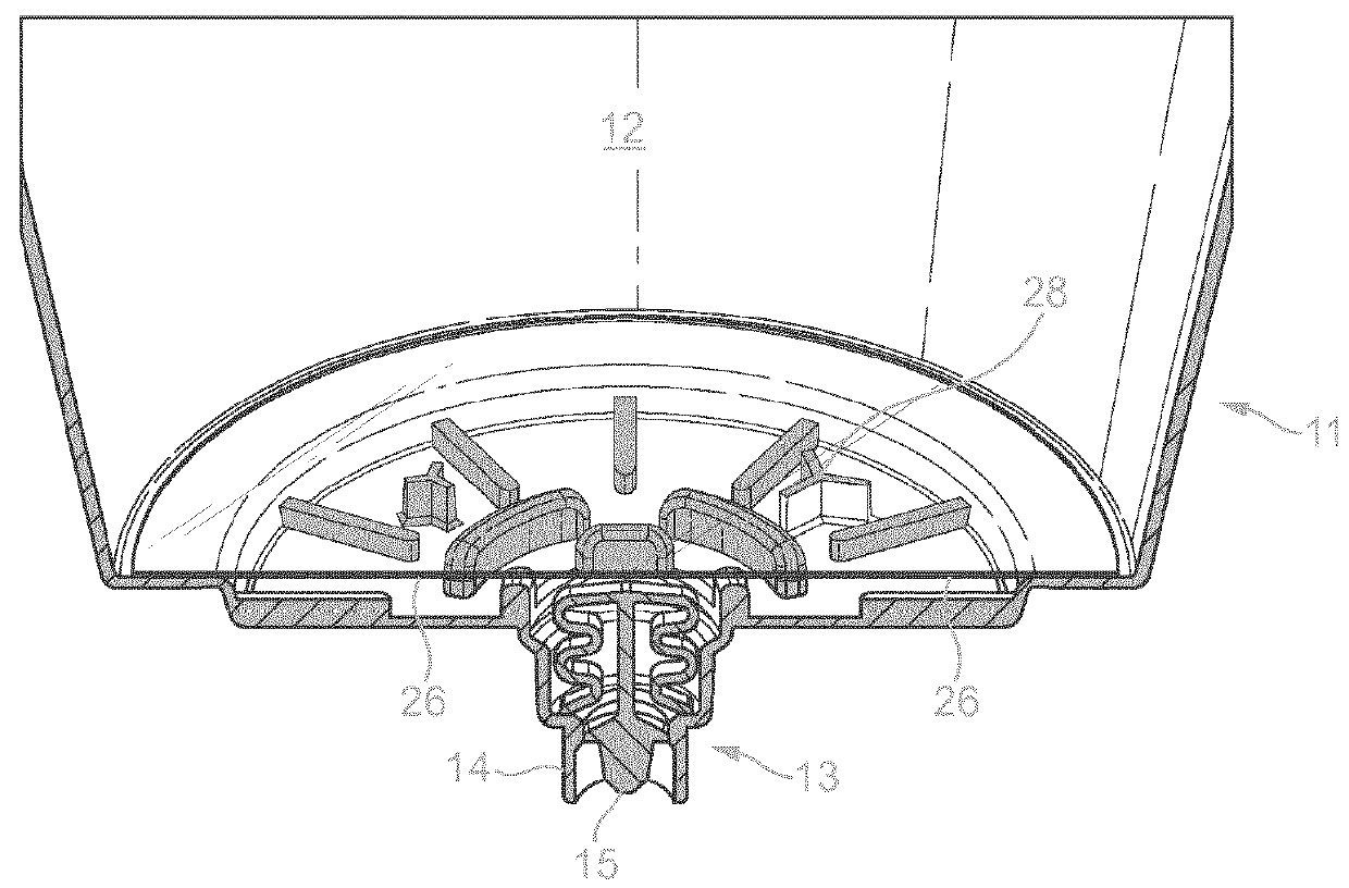
[0055]In the invention illustrated in FIGS. 2 to 7, the spring 16 comprises a pair of deformable wave-shaped spring arms 17. Said spring arms 17 are integrally formed by injection moulding together with the rest of the piston plug, and each of these arms 17 has a longitudinal axis that is substantially parallel to the longitudinal axis of said plug 15.

[0056]As shown in greater detail in FIG. 4, the plug 15 comprises a sealing portion 18 which serves to seal against the inner surface of a corresponding sealing portion 19 of the dispensing channel 14, as illustrated in FIG. 5. The piston plug further comprises a flow-directing portion 20 which serves to direct the flow of beverage out of the capsule, towards the consumer cup, reducing spillage to a great extent. Preferably, the flow-directing portion 20 of the piston plug has a cross-shaped cross section, as illustrated in FIG. 4.

[0057]The distal free ends 21 of the arms 17 are meant to rest upon bearing edges 22 of the dispensing cha...

second embodiment

[0061]In the invention illustrated in FIGS. 8 to 12, the spring 16 comprises three deformable curved arms 23 extending outwardly from the piston plug 15. The spring further comprises a ring 24 connected to the distal ends 25 of said curved arms 23. The ring 24 serves for connecting said piston plug 15 and spring 16 to the rest of the capsule in such a way that said plug and spring are movable relative to the capsule.

[0062]The function of this spring embodiment is similar to that of the first embodiment described above. Again, once the capsule 11 is inserted within the machine and the consumer starts a beverage preparation cycle, water is injected within the capsule under pressure, to mix with the beverage ingredient contained therein. Fluid pressure inside the capsule cavity increases. As pressure builds-up, a force is exerted onto the upper surface of the piston sealing portion 18, which is forced downwards into the dispensing channel 14, while the spring arms 17 are deformed, as i...


PUM


Abstract

The present invention concerns a capsule (11) containing a beverage ingredient, adapted to be functionally inserted in a food preparation machine (1), said capsule comprising walls (12) that define a cavity wherein said beverage is prepared by mixing said ingredient with a fluid injected therein under pressure by said machine, said capsule further comprising a dispensing opening (13), and opening means that open upon effect of the rise of pressure within said cavity, characterized in that said opening means comprise a flow-conducting channel (14) able to connect the capsule cavity to the dispensing opening (13) and a spring-mounted piston plug (15) that is movable in said channel between: (i) a closed position where said cavity pressure is below a first predetermined pressure Pc, the piston spring (16) is at rest, and the piston plug (15) seals against a sealing portion (19) of the channel walls, (ii) a dispensing position where said cavity pressure is equal or superior to Pc, the piston spring (16) is elastically deformed and the piston plug (15) is moved away from the channel walls so that beverage can flow outside of said capsule through said channel (14).

Description

FIELD OF THE INVENTION[0001]The present invention concerns a capsule for use in a food or beverage preparation machine, more precisely, a capsule with anti-dripping properties.BACKGROUND OF THE INVENTION[0002]Beverage preparation machines are well known in the food science and consumer goods area. Such machines allow a consumer to prepare at home a given type of beverage, for instance a coffee-based beverage, e.g. an espresso or a brew-like coffee cup.[0003]Today, most beverage preparation machines for in-home beverage preparation comprise a system made of a machine which can accommodate portioned ingredients for the preparation of the beverage. Such portions can be soft pods or pads, or sachets, but more and more systems use semi-rigid or rigid portions such as rigid pods or capsules. In the following, it will be considered that the beverage machine of the invention is a beverage preparation machine working with a rigid or semi-rigid capsule, such as for instance capsules, sachets,...

Claims


Application Information

Patent Timeline
IPC IPC(8): B65D85/804
CPCB65D85/8043B65D85/8055
Inventor TALON, CHRISTIANHEYDEL, CHRISTOPHE SEBASTIEN PAULBEZET, NICOLAS JEAN-GUY
Owner SOC DES PROD NESTLE SA
Why Eureka
Try Eureka