Rotor and rotor shaft for molten metal

a technology of rotor shaft and molten metal, which is applied in the direction of non-positive displacement fluid engine, waste heat treatment, liquid fuel engine components, etc., can solve the problems of rotor shaft tending to break, rotor moving erratically and failing, and difficult to reverse the threaded end of the sha

Active Publication Date: 2016-02-25
MOLTEN METAL EQUIP INNOVIATIONS LLC
View PDF6 Cites 60 Cited by
  • Summary
  • Abstract
  • Description
  • Claims
  • Application Information

AI Technical Summary

Problems solved by technology

A problem with the couplings, however, is that by applying driving force to the rotor shaft the rotor shaft tends to break at the location where the force is being applied.
Problems with this type of connection are that the threads can fail over time, thereby causing the rotor to move erratically and fail, and it is difficult to reverse the threaded end of the shaft to remove the rotor.
Thus, if the rotor or rotor shaft fail, often both components must be replaced.

Method used


Image

  • Rotor and rotor shaft for molten metal
  • Rotor and rotor shaft for molten metal
  • Rotor and rotor shaft for molten metal

Examples


Embodiment Construction

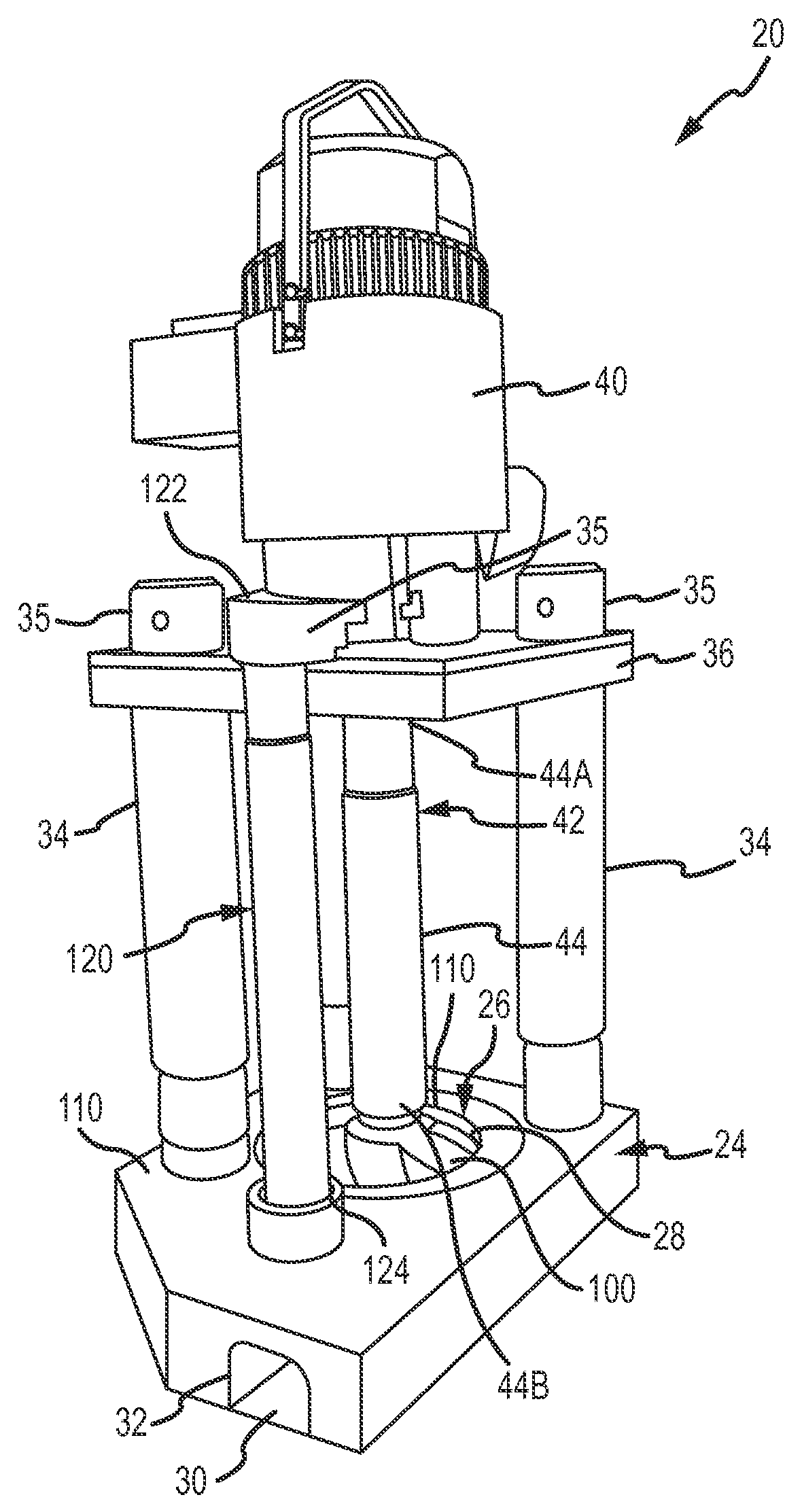
[0027]Referring now to the drawing where the purpose is to illustrate and describe embodiments of the invention, and not to limit same, FIG. 1 shows a molten metal pump 20 that includes a rotor shaft 44 and rotor 100 in accordance with aspects of the present invention. During use, pump 20 is usually positioned in a molten metal bath B in a pump well, which may be part of the open well of a reverbatory furnace.

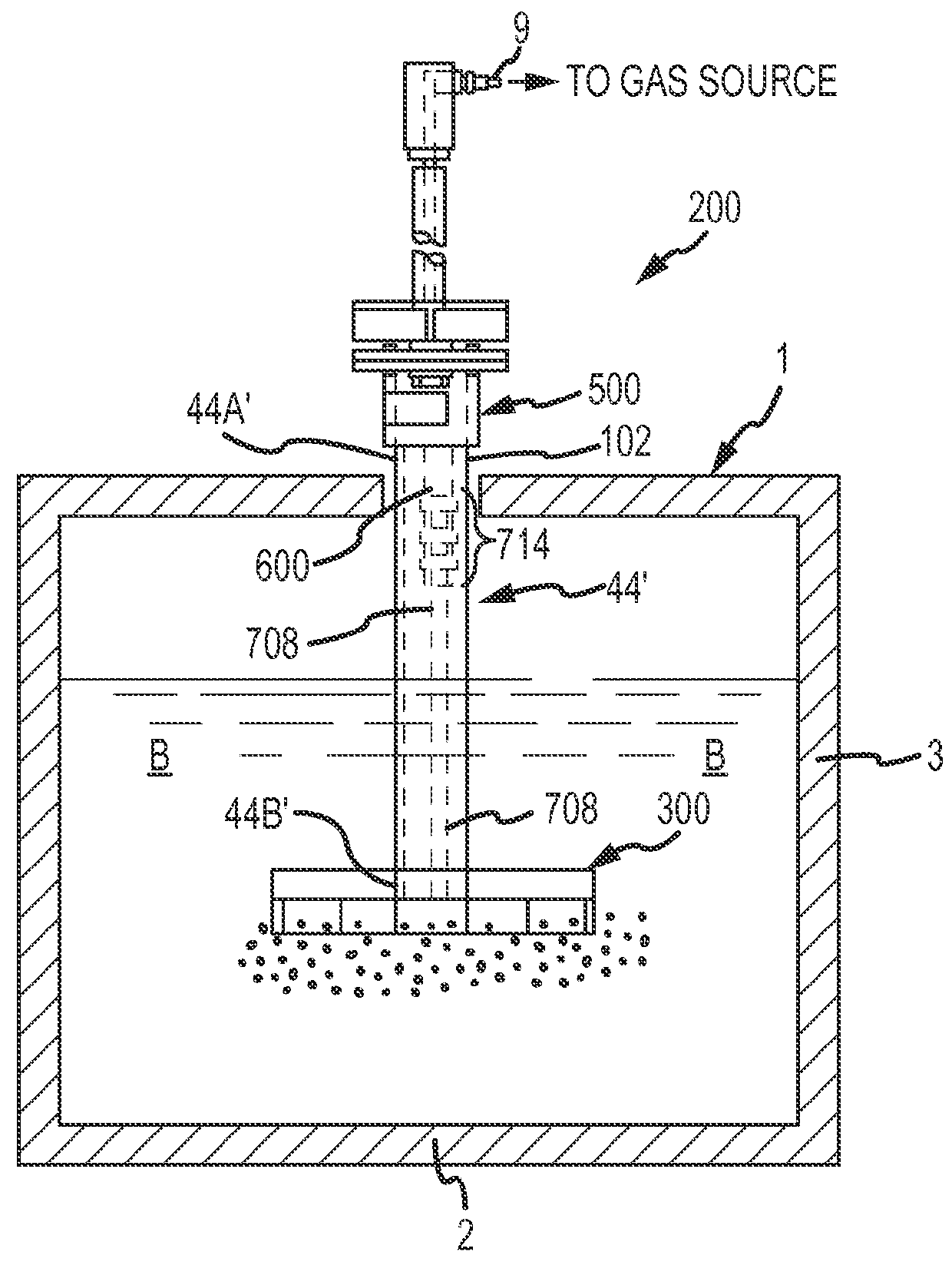
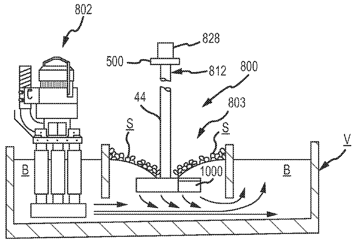
[0028]FIG. 2 shows an example of a rotary degasser that could potentially use a rotor shaft / rotor connection in accordance with aspects of the invention and FIG. 3 shows an example of a scrap melter that could potentially use a rotor shaft / rotor connection in accordance with aspects of the invention. Rotor shaft 44′ of rotary degasser 200 is in all respects the same as rotor shaft 44 described below with respect to the way in which it couples to rotor 300.

[0029]The components of pump 20, including rotor 100, that are exposed to the molten metal are preferably formed of structur...


PUM

PropertyMeasurementUnit
diameteraaaaaaaaaa
widthaaaaaaaaaa
areaaaaaaaaaaa

Abstract

A molten metal rotor receives and retains an end of a molten metal rotor shaft. The rotor shaft has one or more projections at the end received in the rotor. The rotor has an inner cavity, a top surface with an opening leading to the inner cavity, and at least one abutment. The opening includes one or more portions for allowing each projection to pass through the opening and into the inner cavity. The rotor and/or shaft are then rotated so at least one of the outwardly-extending projections is under the top surface of the rotor and is against an abutment. A molten metal pump, rotary degasser scrap melter or other device used in molten metal may utilize a rotor/shaft combination as disclosed herein.

Description

CROSS REFERENCE TO RELATED APPLICATION[0001]This application is a non-provisional of and claims priority to U.S. Provisional Application Ser. No. 62 / 020,332 entitled “Coupling and Rotor Shaft for Molten Metal Devices, filed on Jul. 2, 2014, the contents of which are incorporated herein in its entirety for all purposes.FIELD OF THE INVENTION[0002]The inventions herein relate to devices used in molten metal environments and include (1) a rotor, and (2) a rotor shaft to be connected to the rotor.BACKGROUND OF THE INVENTION[0003]As used herein, the term “molten metal” means any metal or combination of metals in liquid form, such as aluminum, copper, iron, zinc and alloys thereof. The term “gas” means any gas or combination of gases, including argon, nitrogen, chlorine, fluorine, freon, and helium, that are released into molten metal.[0004]Known molten-metal pumps include a pump base (also called a housing or casing), one or more inlets (an inlet being an opening in the housing to allow ...

Claims


Application Information

Patent Timeline
Patent Type & Authority Applications(United States)
IPC IPC(8): F04D7/06C22B9/05F04D1/00F04D13/04F04D13/06F04D29/043F04D29/22F16C3/02F27D3/16F27D27/00
CPCF04D7/065F04D1/00F04D13/04F04D13/06F27D3/16F04D29/043F16C3/02C22B9/055F27D27/005F04D29/22F04D29/20C22B9/00C22B7/003F16D1/10F16D2001/102F27D3/14F27D17/002F27D99/00F27D2099/0083Y02P10/20F16D1/02
Inventor COOPER, PAUL, V.
Owner MOLTEN METAL EQUIP INNOVIATIONS LLC
Why Eureka
Try Eureka