Image processing device, image-capturing device, image processing method, and program

a technology of image processing and image capture, applied in the field of image processing devices, can solve the problems of difficult visual confirmation for users, inability to appropriately confirm the effect of the point-image restoration process for photographic images, and inability to appropriately confirm the effect of the point-image restoration process. to achieve the effect of easy confirmation of the effect of the point-image restoration process

Active Publication Date: 2016-02-25
FUJIFILM CORP
View PDF10 Cites 5 Cited by
  • Summary
  • Abstract
  • Description
  • Claims
  • Application Information

AI Technical Summary

Benefits of technology

[0060]According to the invention, the specific area is highlighted, whereby it is possible to easily confirm the effect of the point-image restoration process, and even when there is noise or the like (saturated pixel or the like) in a photographic image b

Problems solved by technology

However, in the techniques described in JP2009-213044A, JP2004-205802A, and JP2009-77202A, it may not be possible to appropriately confirm the effect of the point-image restoration process for the photographic image.
That is, when confirming the effect of the point-image restoration process, it may be difficult for the user to visually confirm the effect simply by arranging and displaying a photographic image before a point-image restoration process and

Method used


Image

  • Image processing device, image-capturing device, image processing method, and program
  • Image processing device, image-capturing device, image processing method, and program
  • Image processing device, image-capturing device, image processing method, and program

Examples


modification example 1

of Image Processing Device

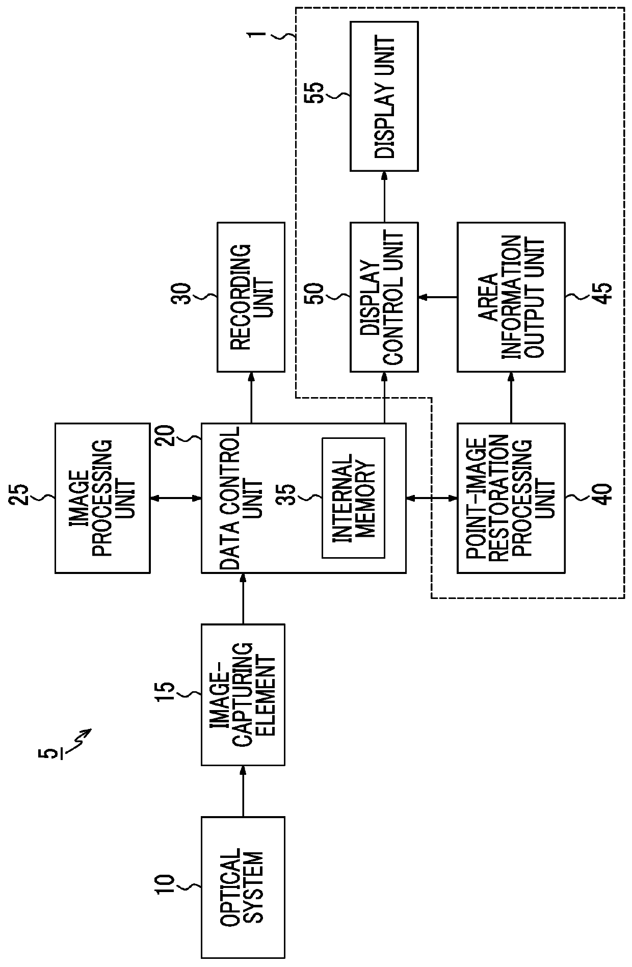
[0132]FIG. 11 is a block diagram showing main parts of Modification Example 1 of the image processing device 1. When comparing the image processing device 1 shown in FIG. 1 and the image processing device 1 shown in FIG. 11, the image processing device 1 shown in FIG. 11 has a filter area information output unit 46 instead of the area information output unit 45 in the image processing device 1 shown in FIG. 1. Hereinafter, the image processing device 1 shown in FIG. 11 will be described in detail. The same main parts as those in FIG. 1 are represented by the same reference numerals, and description thereof will not be repeated.

[0133]The filter area information output unit 46 receives information relating to the restoration filter of the point-image restoration process as input and outputs filter area information relating to the specific area 110 in the restored image based on information relating to the restoration filter. Information relating to the restor...

modification example 2

of Image Processing Device

[0142]FIG. 14 is a block diagram showing main parts of Modification Example 2 of the image processing device 1. When comparing the image processing device 1 shown in FIG. 1 and the image processing device 1 shown in FIG. 14, the image processing device 1 shown in FIG. 14 has an analysis area information generation unit 47 instead of the area information output unit 45 in the image processing device 1 shown in FIG. 1. Hereinafter, Modification Example 2 of the image processing device 1 shown in FIG. 14 will be described in detail. The same main parts as those in FIG. 1 are represented by the same reference numerals, and description thereof will not be repeated.

[0143]The analysis area information generation unit 47 acquires the photographic image retained in the data control unit 20, analyzes and specifies an area where a false signal is likely to occur in the photographic image, sets the area as the specific area 110, and generates the analysis area informat...

modification example 3

of Image Processing Device

[0149]FIG. 16 is a block diagram showing main parts of Modification Example 3 of the image processing device 1. When comparing the image processing device 1 shown in FIG. 1 and the image processing device 1 shown in FIG. 16, the image processing device 1 shown in FIG. 16 has a photographing condition area information output unit 48 instead of the area information output unit 45 in the image processing device 1 shown in FIG. 1. Hereinafter, Modification Example 3 of the image processing device 1 shown in FIG. 16 will be described in detail. The same main parts as those in FIG. 1 are represented by the same reference numerals, and description thereof will not be repeated.

[0150]The photographing condition area information output unit 48 receives information relating to the photographing conditions of the photographic image from the optical system 10 as input and outputs photographing condition area information relating to the specific area 110 in the photograp...


PUM


Abstract

An image processing device includes a point-image restoration processing unit 40 which receives a photographic image as input, and subjects the photographic image to a point-image restoration process based on point-image restoration information to generate a restored image, an area information output unit 45 which outputs area information relating to a specific area in the restored image where restoration strength of the point-image restoration process based on the point-image restoration information is equal to or greater than a threshold value, a display control unit 50 which receives the restored image and the area information as input and performs display control to highlight the specific area in the restored image based on the area information, and a display unit 55 which highlights at least the specific area based on the display control by the display control unit 50.

Description

CROSS-REFERENCE TO RELATED APPLICATIONS[0001]This application is a Continuation of PCT International Application No. PCT / JP2014 / 059163 filed on Mar. 28, 2014, which claims priority under 35 U.S.C §119(a) to Japanese Patent Application No. 2013-101485 filed May 13, 2013. Each of the above application(s) is hereby expressly incorporated by reference, in its entirety, into the present application.BACKGROUND OF THE INVENTION[0002]1. Field of the Invention[0003]The present invention relates to a technique for an image processing device, and in particular, a technique for display of an image subjected to correction based on a point spread function (PSF).[0004]2. Description of the Related Art[0005]Image deterioration or diffraction blur resulting from various types of aberration for an optical system (photographing lens and the like) may occur in a photographic image obtained by photographing an object by an image-capturing device, such as a digital camera.[0006]In order to prevent image ...

Claims


Application Information

Patent Timeline
IPC IPC(8): G06T5/00H04N5/357
CPCG06T5/003G06T2207/20024G06T2207/20201H04N5/3572H04N23/959H04N23/635H04N25/615H04N25/6153H04N23/843H04N25/134
Inventor HAYASHI, KENKICHISUGIMOTO, MASAHIKONARUSE, YOUSUKE
Owner FUJIFILM CORP
Why Eureka
Try Eureka