Hybrid Flow Control Method

a flow control and hybrid technology, applied in the direction of machines/engines, transportation and packaging, aircraft power plants, etc., can solve the problems of complex flow field, high unsteady interaction, complicated flow field,

Inactive Publication Date: 2016-03-03
FLORIDA STATE UNIV RES FOUND INC
View PDF10 Cites 5 Cited by
  • Summary
  • Abstract
  • Description
  • Claims
  • Application Information

AI Technical Summary

Benefits of technology

[0013]The present invention comprises a hybrid flow control system and method used to reduce unsteadiness produced when a jet of fluid flow impinges upon a surface. The hybrid system comprises providing an array of equally spaced microjets placed around the periphery of the nozzle exit that issue fluid into the main jet flow. The fluid can be compressible or incompressible (for the main jet and microjet flow). In the case of a Vertical / Short-Takeoff and Landing aircraft, the microjets can be actuated during takeoff or landing by a sensor or a crewmember. A similar approach can be employed during takeoff from an aircraft carrier deck.

Problems solved by technology

An S / VTOL aircraft in hover or a fighter aircraft taking off from an aircraft carrier creates a complicated flow field.
The flow field is complicated due to the high velocity of the jet issuing from the aircraft coupled with the interaction of the jet with a surface.
This interaction is highly unsteady, especially in the S / VTOL hover configuration. FIG. 1 shows a schematic of a prior art S / VTOL aircraft in hover.
The nature of the flow field created by an aircraft in hover creates multiple adverse effects, which include high noise levels, unsteady acoustic loads, sonic fatigue on the aircraft and surrounding structures, ground erosion, ingestion of hot gases into the engine nacelle and lift loss of the aircraft.
This is also problematic in the case of a plane taking off from an aircraft carrier.
While this does protect workers on the deck from the blast of the jet, the noise levels generated are exceedingly high.
These noise levels are extremely detrimental and cause a serious health concern for personnel working on the deck of the carrier.
This phenomenon creates strong acoustic waves which create a resonance that is the source of the high noise levels.
Previous methods have been successful in flow control and noise reduction, but the prior attempts at active control require a much higher percentage of the jet momentum than the present system.

Method used


Image

  • Hybrid Flow Control Method
  • Hybrid Flow Control Method
  • Hybrid Flow Control Method

Examples


Embodiment Construction

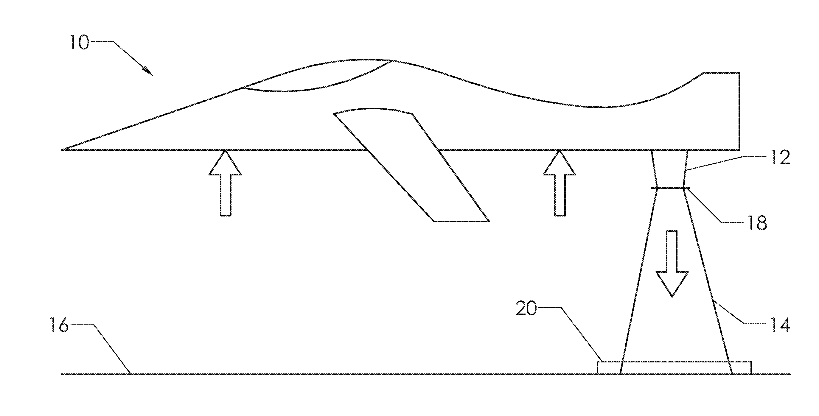
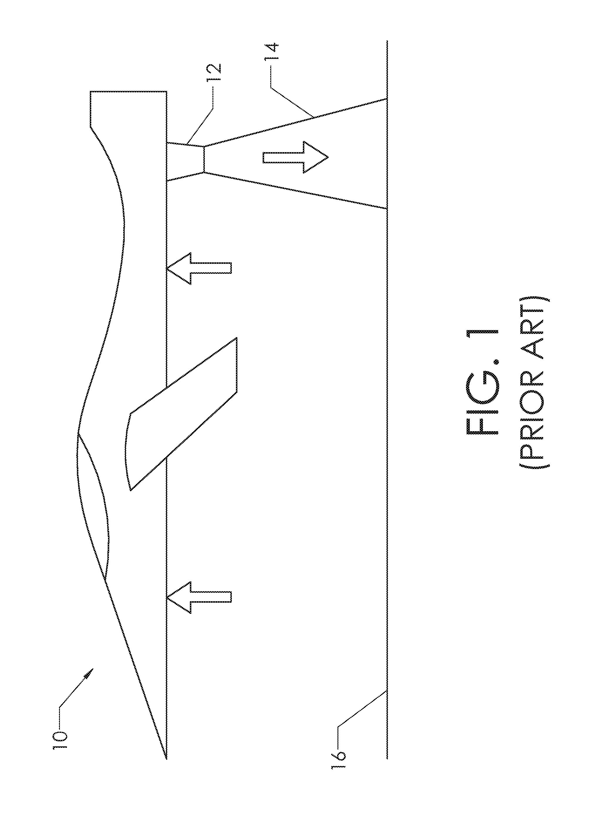
[0026]FIG. 1 shows a schematic of a prior art S / VTOL aircraft in hover. As discussed in the preceding text, main jet flow 14 issues from main jet nozzle 12. Main jet flow 14 impinges on surface 16, which creates lift. The forces created are indicated by the arrows in the figure. The reader should note that aircraft 10 can be taking off landing or simply hovering above surface 16. Aircraft 10 takes off when main jet flow 14 acts on surface 16 with enough thrust to lift aircraft 10 from surface 16.

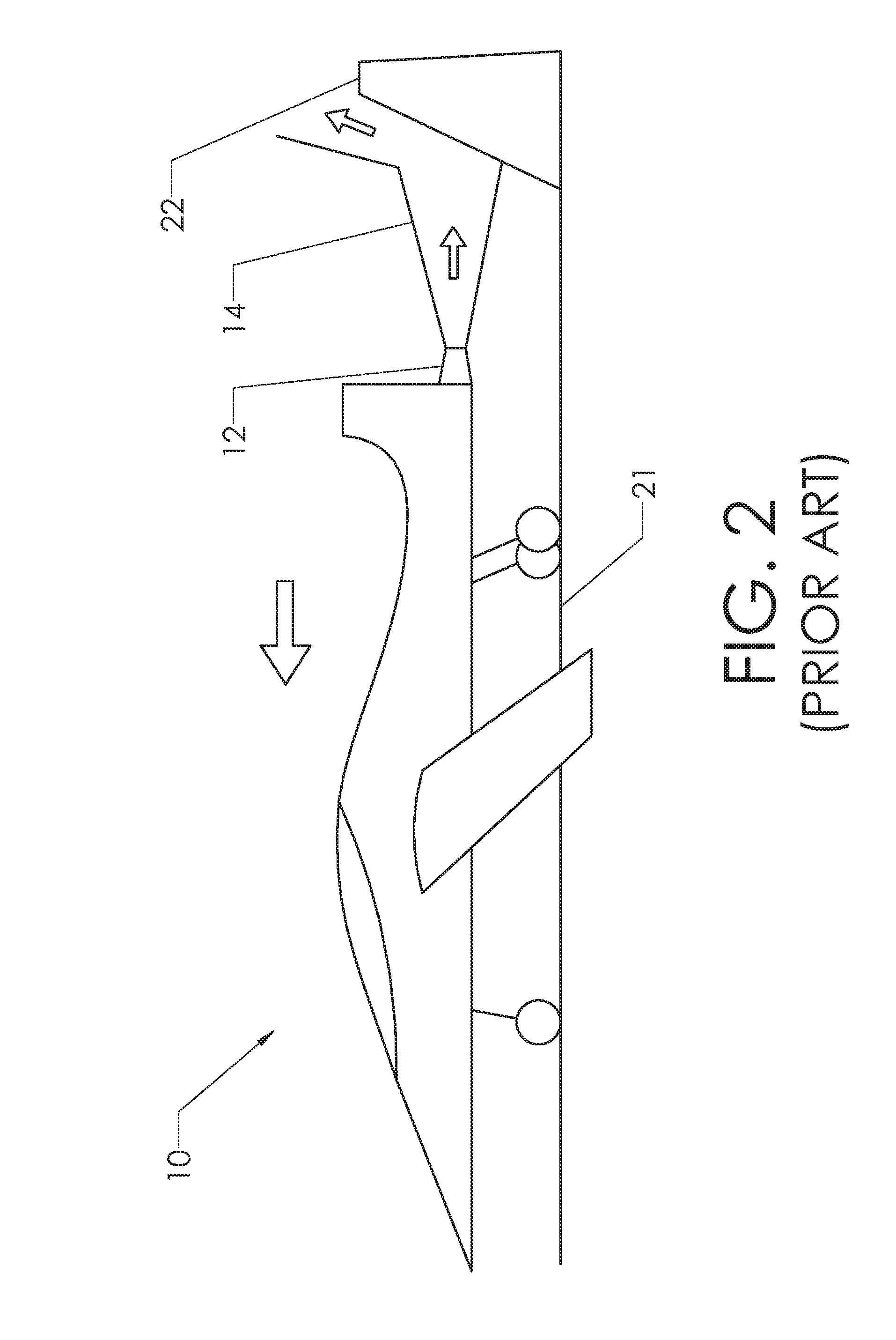
[0027]FIG. 2 shows aircraft 10 taking off from aircraft carrier deck 21. Similar to FIG. 1, the reader can see that main jet 14 impinges upon a surface. In this case, the surface is blast deflector 22. As demonstrated by the arrows within main jet 14, blast deflector 22 redirects the flow up and away from any equipment or personnel that may be on deck 21.

[0028]A V / STOL aircraft in hover and a fighter jet taking off from an aircraft carrier (using a blast deflector) have been highly studied t...


PUM


Abstract

A system for controlling flow unsteadiness and noise reduction. One or more microjets are placed around the periphery of a jet nozzle in conjunction with a porous surface acting as the impingement surface. As an aircraft is taking off or landing, vertically, the microjets are activated to inject a stream of high-velocity fluid into the shear layer of the main jet at an angle from the main jet centerline. The microjets disrupt the feedback phenomenon, reducing the resonant-dominated aspect of the flow while the porous surface breaks up the coherence of the jet and reduces the broadband noise of the flow.

Description

CROSS-REFERENCES TO RELATED APPLICATIONS[0001]This non-provisional patent application claims the benefit of an earlier-filed provisional patent application. The provisional application was assigned Ser. No. 61 / 807,930. It was filed on Apr. 3, 2013.STATEMENT REGARDING FEDERALLY SPONSORED RESEARCH OR DEVELOPMENT[0002]Not ApplicableMICROFICHE APPENDIX[0003]Not ApplicableBACKGROUND OF THE INVENTION[0004]1. Field of the Invention[0005]The invention relates to the field of flow control in a fluid. More specifically, the invention comprises the use of properly placed microjets coupled with a porous impingement surface to control flow unsteadiness in the flow field of a jet impinging on a surface.[0006]2. Description of Related Art[0007]The impingement of a jet of fluid on a surface is a commonly occurring phenomenon. It takes place in the context of cooling electronics, the launching of a rocket or space shuttle, a fighter jet taking off of an aircraft carrier (using a blast deflector), a ...

Claims


Application Information

Patent Timeline
Patent Type & Authority Applications(United States)
IPC IPC(8): F02K1/34F02K1/82
CPCF02K1/82F02K1/34
Inventor KUMAR, RAJANALVI, FARRUKH
Owner FLORIDA STATE UNIV RES FOUND INC
Why Eureka
Try Eureka