
Heated Flow Conditioning Systems And Methods of Using Same

Active Publication Date: 2016-03-03
CANADA PIPELINE ACCESSORIES
View PDF7 Cites 14 Cited by
  • Summary
  • Abstract
  • Description
  • Claims
  • Application Information

AI Technical Summary

Benefits of technology

The invention describes a method to prevent solid buildup in a flow conditioning system. The method involves heating the system with a heated medium to a minimum temperature at which solid formation cannot occur. This heated medium is then circulated through the system to prevent solid buildup. The technical effect of this patent text is to provide a solution to prevent blockages in flow conditioning systems that can cause damage and reduce efficiency.

Problems solved by technology

As such, one issue involves the management of solid depositions including, but not limited to, wax formation, hydrate formation, or asphaltene deposition during operations, planned and / or emergency shutdowns, and prior to startups after any prolonged shutdown.
In particular, solids deposition may be an issue in climates, such as in northern Europe, northern North America, or at high altitudes, where the fluid in pipelines is colder than in more southern climates.
Hydrate formation and accumulation can potentially block the passage of fluids altogether and detrimentally affect system performance.
Moreover, although flow conditioners can be generally used to correct the flow profile of the fluid such that it forms a fully-developed flow profile, flow conditioners are generally incapable of minimizing or preventing adverse solid buildup or deposition.

Method used


Image

  • Heated Flow Conditioning Systems And Methods of Using Same
  • Heated Flow Conditioning Systems And Methods of Using Same
  • Heated Flow Conditioning Systems And Methods of Using Same

Examples


Embodiment Construction

[0030]Flow conditioners are generally designed to create a swirl-free or a fully-developed flow profile at a certain flow position, for example, at a metering device or station.

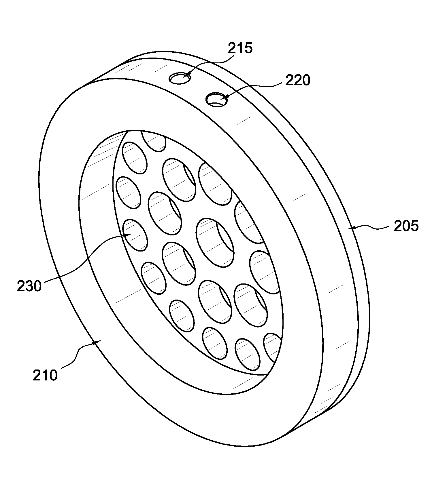
[0031]Several types of flow conditioners exist including, but not limited to, straightening vanes, tube bundles, and perforated plates. A perforated plate flow conditioner may include a perforated plate that is arranged within a pipe orthogonal to the fluid flow (i.e., across a cross section of pipe). The perforations or holes in the flow conditioner cause the fluid flow to be redistributed such that it forms a fully-developed flow profile.

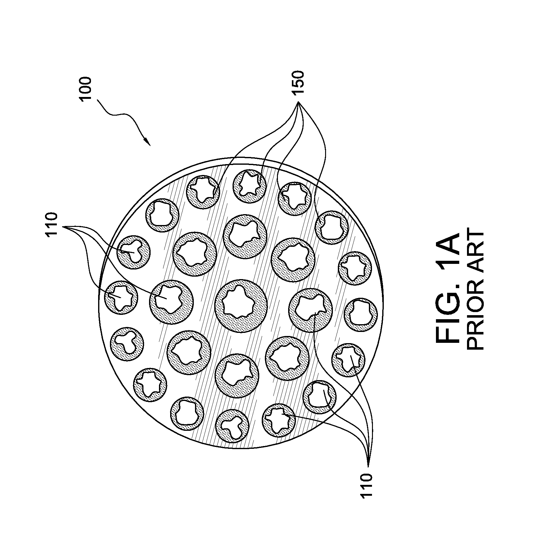
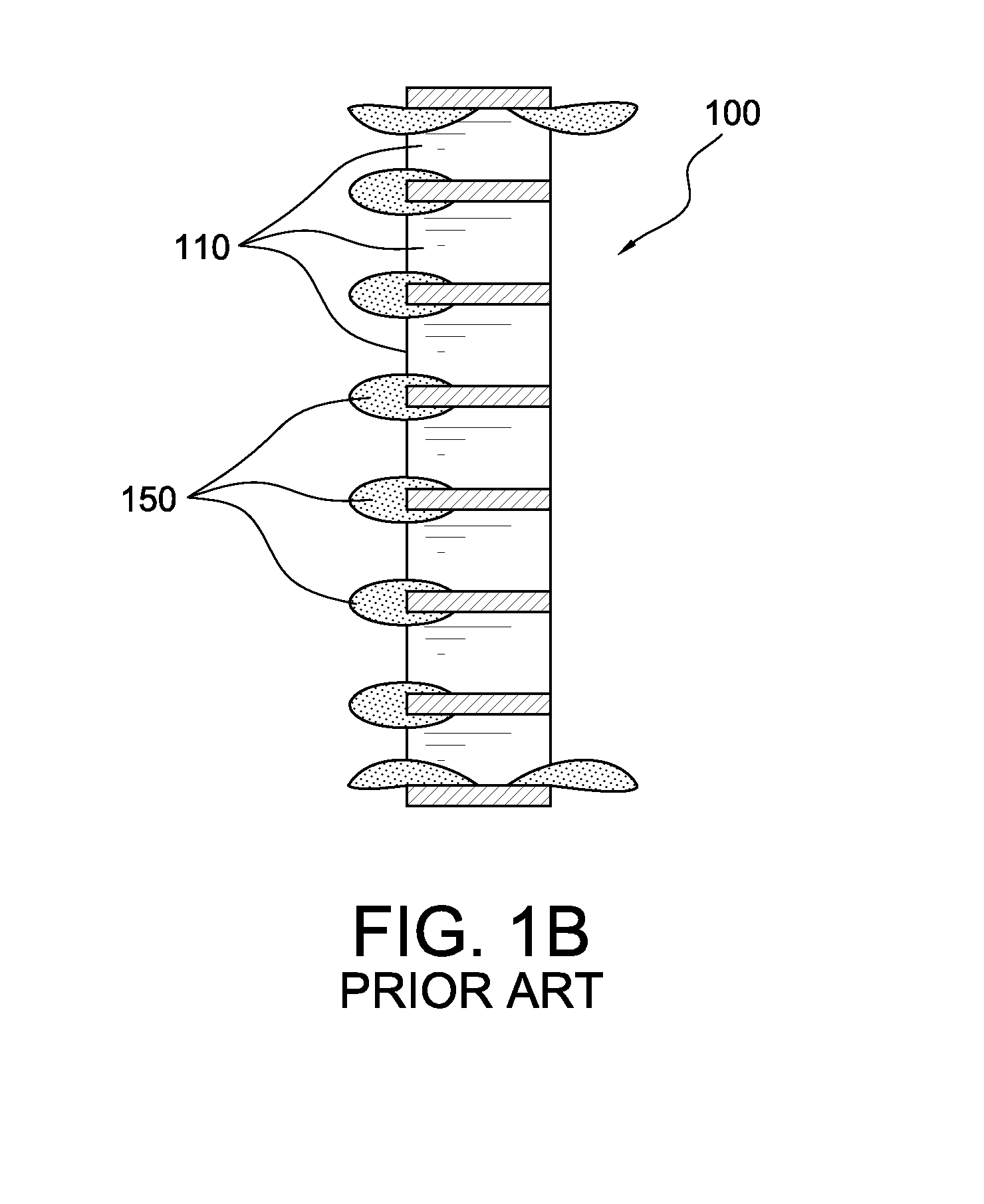
[0032]Fluid flow measurement systems comprising such flow conditioners have been found to exhibit appreciable degradation in system accuracy over time. This degradation in system accuracy may be the result of the buildup of solid deposits on any at least one of a flow conditioner, a pipe, a meter, other system components, or any combination thereof.

[0033]Deposits on the sys...


PUM


Abstract

A heated flow conditioning system includes a flow conditioner comprising a plurality of apertures and a flange, the flange surrounding said plurality of holes and comprising a first open-ended groove; and a spacer ring comprising a second open-ended groove. The first and the second open-ended grooves are configured to be connectable to each other, thereby forming a fluid channel for at least one heating medium.

Description

[0001]The present application claims priority to U.S. provisional application Ser. No. 62 / 044,485 filed on 2 Sep. 2014, the entirety of which is incorporated herein by reference.FIELD OF THE INVENTION[0002]The present invention relates to fluid flow conditioning systems. More particularly, the present invention relates to heated flow conditioning systems capable of reducing the buildup of solids and related methods.BACKGROUND OF THE INVENTION[0003]Pipelines are used to transport fluids in various industries, including chemical, oil and gas, and manufacturing industries. These industries use processes that require accurate measurements of fluid flow rates. Measurements can be taken at locations such as a meter station.[0004]Meters that are used to measure fluid flow rates can function in several different ways. For example, meters can use any one of the following to measure fluid flow rates: (1) differential pressure of the fluid across an obstruction, (2) ultrasonic signal travel ti...

Claims


Application Information

Patent Timeline
IPC IPC(8): F16L55/027
CPCF16L55/02709F16L23/003F16L55/02718F15D1/025F15D1/001F16L53/00F15D1/00F16L23/00F16L55/027G01F1/42F15D1/0005
Inventor SAWCHUK, DANIEL, A.SELIRIO, REGINALD
Owner CANADA PIPELINE ACCESSORIES
Learn More