Horizontal spiral discharge settling centrifuge

A settling centrifuge, horizontal screw technology, applied to centrifuges, centrifuges with rotating drums, etc., can solve the problems of worn blades, increased equipment operating costs and maintenance costs, increased thickness of solid slag piles, etc., to achieve Effects of preventing solid phase accumulation, reducing maintenance and operating costs, and avoiding wear and tear

Inactive Publication Date: 2014-02-05
JIANGSU HENGLIANG CENTRIFUGE MFG
6 Cites 3 Cited by

AI-Extracted Technical Summary

Problems solved by technology

However, after the separator is added, the viscous sand and gravel will accumulate near the separator to form a solid slag pile. After a long time, it will wear the blade after reaching a certain thick...

Method used

As shown in Figure 1 and Figure 2, a kind of horizontal spiral unloading sedimentation centrifuge of the present invention, comprises drum 1 and screw rod 2, has the blade 21 of spiral setting on the described screw rod 2, drum 1 The outer cover is provided with a housing 3, and one end of the housing 3 is provided with a feed port 31 that communicates with the inner cavity of the screw rod 2. The lower end of the housing 3 is provided with a liquid discharge port 32 at one end close to the feed...

Abstract

The invention relates to a horizontal spiral discharge settling centrifuge which comprises a revolving drum and a screw; spiral blades are arranged on the screw; a housing covers the revolving drum; a feed opening communicated with the inner cavity of the screw is formed in one end of the housing; a liquid outlet is formed in one end, close to one end of the feed opening, of the lower end of the housing; a bleed hole is formed in the other end; at least 20 grooves are formed in the inner wall of the revolving drum in the circumferential direction. The grooves are formed in the inner wall of the revolving drum to prevent a liquid phase from forming a water film and a solid phase from accumulation, the abrasion of the blade is avoided, and the normal work of the blade is not influenced even if part of the solid phase is accumulated in the grooves.

Application Domain

Technology Topic

Image

  • Horizontal spiral discharge settling centrifuge
  • Horizontal spiral discharge settling centrifuge

Examples

  • Experimental program(1)

Example Embodiment

[0016] The present invention will now be described in further detail with reference to the drawings. These drawings are all simplified schematic diagrams, which merely illustrate the basic structure of the present invention in a schematic manner, so they only show the structures related to the present invention.
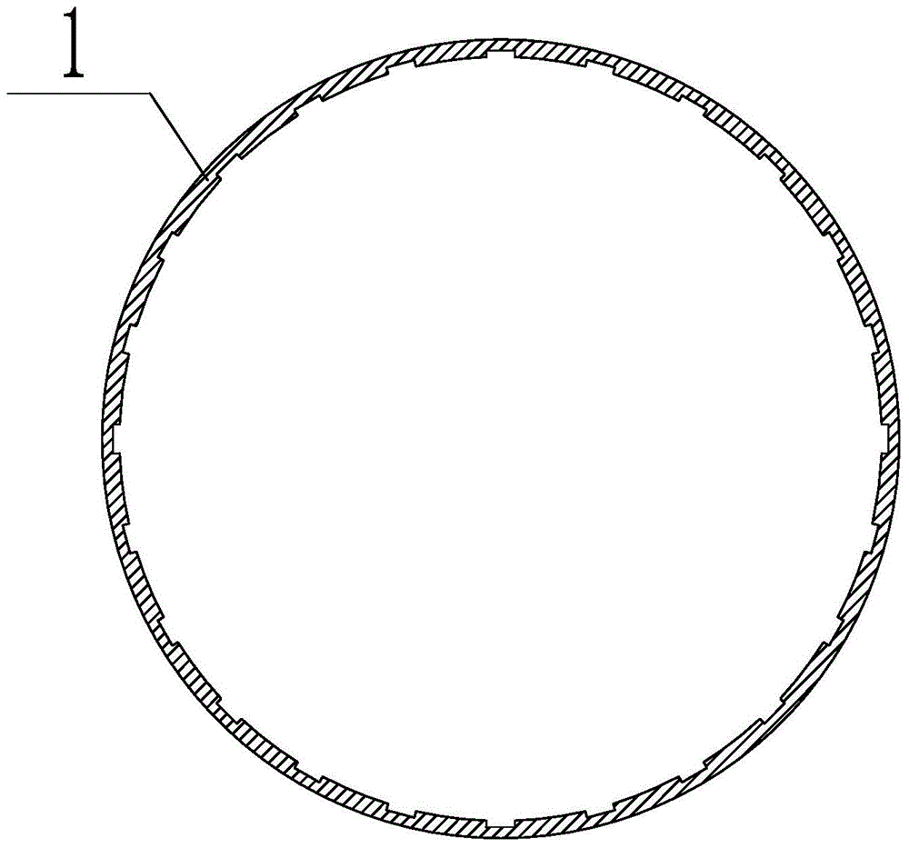
[0017] Such as figure 1 with figure 2 As shown, a horizontal spiral unloading sedimentation centrifuge of the present invention includes a rotating drum 1 and a screw 2. The screw 2 has spirally arranged blades 21, and the outer cover of the rotating drum 1 is provided with a shell 3, and the shell 3 is provided with a feed port 31 communicating with the inner cavity of the screw 2, the lower end of the housing 3 is provided with a liquid discharge port 32 at one end close to the feed port 31, and a slag discharge port 33 at the other end. The inner wall of the drum 1 is provided with at least 20 grooves along the circumferential direction. By opening a plurality of grooves on the inner wall of the drum 1, it can prevent the liquid phase from forming a water film and prevent the solid phase from accumulating, thus avoiding the wear of the blade 21. The solid phase will partially accumulate in the grooves, but not Affect the normal operation of the blade.
[0018] In an embodiment of the groove, the radial cross-sectional shape of the groove is rectangular.
[0019] In an embodiment of the groove, the radial cross-sectional shape of the groove is an arc shape.
[0020] Specifically, the inner diameter of the rotating drum 1 is 530 mm, and the number of grooves on the inner wall of the rotating drum 1 is 24-36.
[0021] Preferably, the 24-36 grooves are evenly arranged on the inner wall of the drum 1 along the circumferential direction.
[0022] Taking the above-mentioned ideal embodiment according to the present invention as enlightenment, through the above-mentioned description content, relevant staff can make various changes and modifications without departing from the scope of the technical idea of ​​the present invention. The technical scope of the present invention is not limited to the content of the description, and its technical scope must be determined according to the scope of the claims.

PUM

PropertyMeasurementUnit
The inside diameter of530.0mm
tensileMPa
Particle sizePa
strength10

Description & Claims & Application Information

We can also present the details of the Description, Claims and Application information to help users get a comprehensive understanding of the technical details of the patent, such as background art, summary of invention, brief description of drawings, description of embodiments, and other original content. On the other hand, users can also determine the specific scope of protection of the technology through the list of claims; as well as understand the changes in the life cycle of the technology with the presentation of the patent timeline. Login to view more.

Similar technology patents

Tackle for paying off underground laid cable

InactiveCN103618261AEasy to useAvoid wear and tearCable installations in underground tubesApparatus for laying cablesEngineeringPulley
Owner:STATE GRID CORP OF CHINA +1

Classification and recommendation of technical efficacy words

Why Eureka
Try Eureka