Optically pumped atomic magnetometer and magnetic sensing method

a technology of atomic magnetometer and magnetic sensing method, which is applied in the field of sensing method and magnetometer, can solve the problem of increasing the size of the apparatus

Active Publication Date: 2016-03-03
CANON KK
View PDF4 Cites 70 Cited by
  • Summary
  • Abstract
  • Description
  • Claims
  • Application Information

AI Technical Summary

Benefits of technology

[0007]An object of the present invention is to provide an optically pumped atomic magnetometer and a magnetic sensing method that can separate and measure magnetic information of spatially different places at the same time by one probe beam.

Problems solved by technology

Furthermore, a detector of signal is necessary for each cell, and there is a problem that the size of the apparatus is increased.

Method used


Image

  • Optically pumped atomic magnetometer and magnetic sensing method
  • Optically pumped atomic magnetometer and magnetic sensing method
  • Optically pumped atomic magnetometer and magnetic sensing method

Examples


first embodiment

[0030]An optically pumped atomic magnetometer and a magnetic sensing method according to a first embodiment of the present invention will be described with reference to FIGS. 1 to 4.

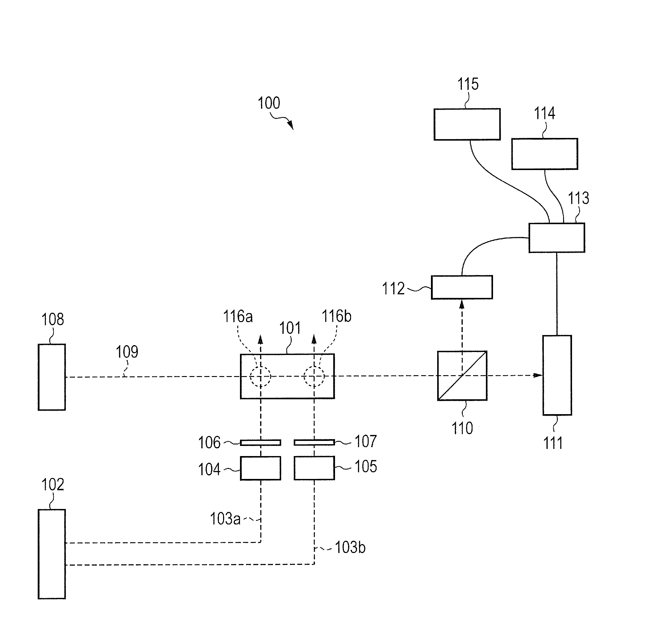
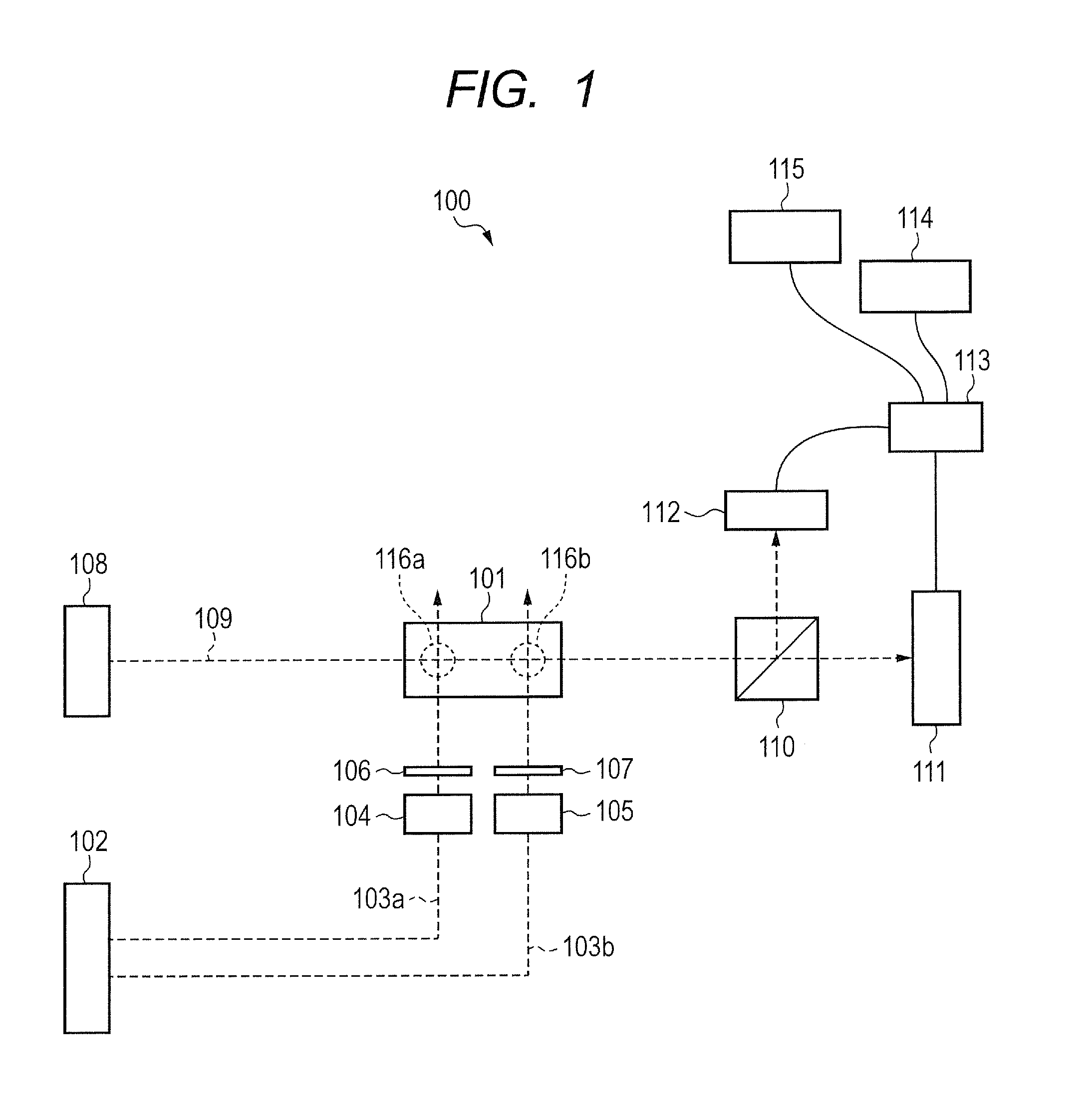
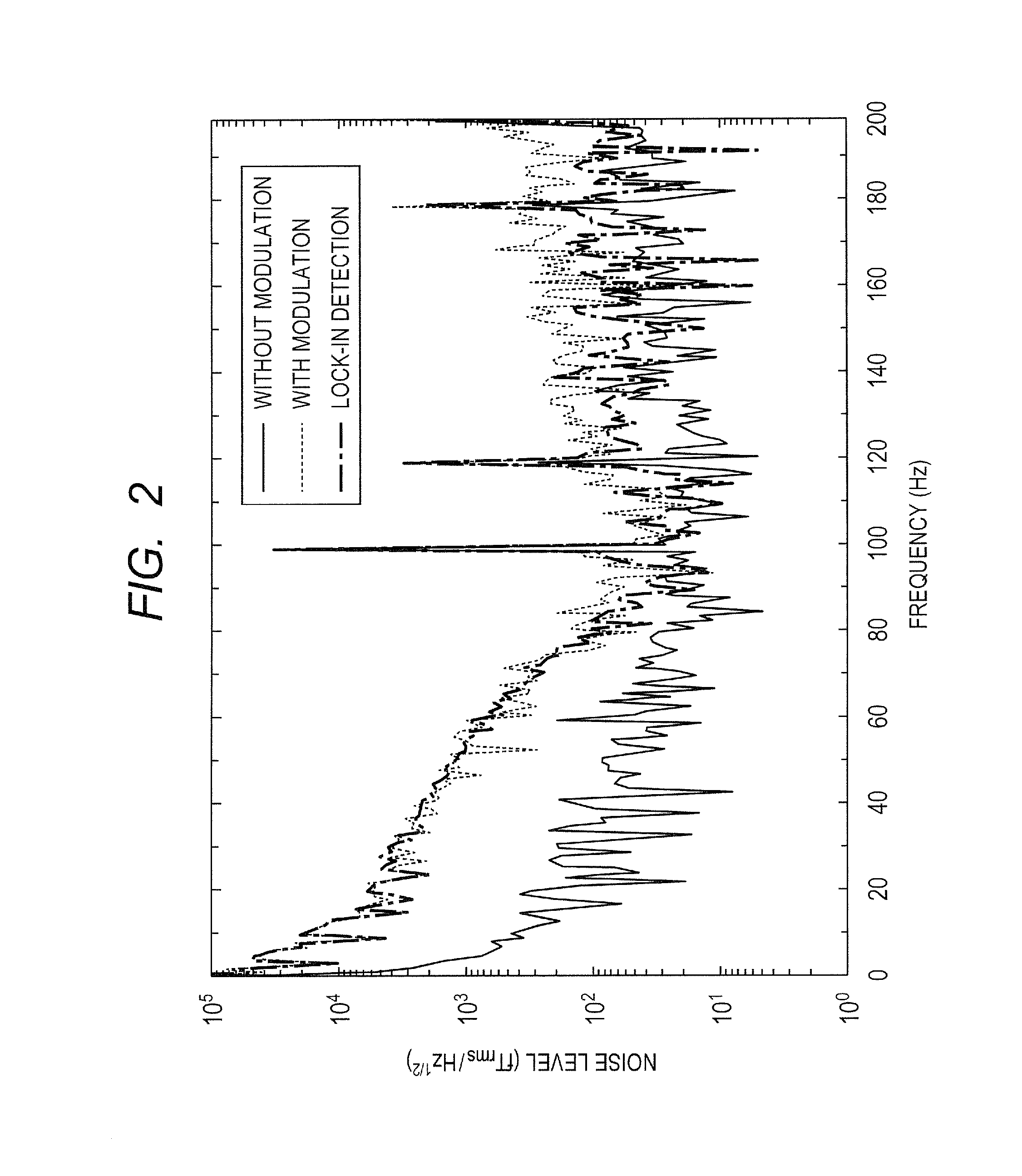
[0031]FIG. 1 is a schematic diagram illustrating a configuration of the optically pumped atomic magnetometer according to the present embodiment. FIGS. 2 to 4 are diagrams illustrating an example of results of measurement using the optically pumped atomic magnetometer according to the present embodiment.

[0032]First, a schematic configuration of the optically pumped atomic magnetometer according to the present embodiment will be described with reference to FIG. 1.

[0033]As illustrated in FIG. 1, an optically pumped atomic magnetometer 100 according to the present embodiment includes a cell 101, a pump beam optical system 102, optical modulators 104 and 105, phase retarders 106 and 107, and a probe beam optical system 108. The optically pumped atomic magnetometer 100 also includes a polarization separation ...

second embodiment

[0059]An optically pumped atomic magnetometer and a magnetic sensing method according to a second embodiment of the present invention will be described with reference to FIGS. 5 to 6D. The same constituent elements as in the optically pumped atomic magnetometer according to the first embodiment illustrated in FIGS. 1 to 4 are expressed by the same names, and the description will be omitted or simplified. The description of the same constituent elements in the embodiments can be applied to each other within a range not contrary to the configurations specific to the embodiments.

[0060]FIG. 5 is a schematic diagram illustrating a configuration of the optically pumped atomic magnetometer according to the present embodiment. FIGS. 6A to 6D are schematic diagrams illustrating an example of a modulation method of pump beam.

[0061]First, a schematic configuration of the optically pumped atomic magnetometer according to the present embodiment will be described with reference to FIG. 5.

[0062]As...

third embodiment

[0115]An optically pumped atomic magnetometer and a magnetic sensing method according to a third embodiment of the present invention will be described with reference to FIG. 5 and FIGS. 7A to 7C. The same constituent elements as in the optically pumped atomic magnetometer according to the first and second embodiments illustrated in FIGS. 1 to 6D are expressed by the same names, and the description will be omitted or simplified. The description of the same constituent elements in the embodiments can be applied to each other within a range not contrary to the configurations specific to the embodiments.

[0116]First, a schematic configuration of the optically pumped atomic magnetometer according to the present embodiment will be described with reference to FIG. 5.

[0117]The optically pumped atomic magnetometer according to the present embodiment is the same as the optically pumped atomic magnetometer according to the second embodiment illustrated in FIG. 5, except that the demodulators 22...


PUM


Abstract

Provided is an optically pumped atomic magnetometer that can separate and acquire magnetic information of spatially different places at the same time by one probe beam. The optically pumped atomic magnetometer includes a cell containing alkali metal atoms, a pump beam optical system introducing pump beams including circularly polarized light component to different locations of the cell, a probe beam optical system introducing a probe beam including linearly polarized light component to the cell, a detection unit detecting a signal reflecting a rotation angle of a plane of polarization of the probe beam after intersecting with the pump beams, and an information acquisition unit acquiring information related to a magnetic field intensity of each of the different locations from the detected signal. The pump beam optical system includes a modulation unit modulating the pump beams so that one of frequencies and phases of the pump beams is different.

Description

BACKGROUND OF THE INVENTION[0001]1. Field of the Invention[0002]The present invention relates to a sensing method and a magnetometer that measure magnetic field intensity, and particularly, to an optically pumped atomic magnetometer and a magnetic sensing method using electron spin or nuclear spin of atoms.[0003]2. Description of the Related Art[0004]Optically pumped atomic magnetometers are described in Non Patent Literature 1 (Yosuke Ito, et al., “Magnetic field distribution measurements with an optically pumped atomic magnetometer using a hybrid cell of K and Rb atoms for biomagnetic measurements”, IEICE, Vol. 112, No. 479, MBE 2012-93, p. 31, March 2013) and Patent Literature 1 (Japanese Patent Application Laid-Open No. 2011-203133). The optically pumped atomic magnetometer described in Non Patent Literature 1 includes a cell containing alkali metal gas, a light source for pump beam (pump light, pump light beam) and a light source for probe beam (probe light, probe light beam). ...

Claims


Application Information

Patent Timeline
Patent Type & Authority Applications(United States)
IPC IPC(8): G01R33/26
CPCG01R33/26
Inventor KOBAYASHI, TETSUOITO, YOSUKEICHIHARA, SUNAOMIZUTANI, NATSUHIKO
Owner CANON KK
Why Eureka
Try Eureka