
Multi-channel optical module and manufacturing method thereof

a manufacturing method and optical module technology, applied in the field can solve the problems of requiring a large amount of manufacturing time and cost, less precise and reliable, etc., and achieve the effects of reducing the manufacturing cost of multi-channel optical modules, minimizing optical signal loss, and improving the efficiency of optical coupling between elements

Inactive Publication Date: 2016-03-03
ELECTRONICS & TELECOMM RES INST
View PDF20 Cites 1 Cited by
  • Summary
  • Abstract
  • Description
  • Claims
  • Application Information

AI Technical Summary

Benefits of technology

The present disclosure provides a multi-channel optical module and manufacturing method that can minimize optical signal loss and reduce manufacturing cost. The module combines passive alignment and active alignment to improve optical coupling efficiency and minimize optical signal loss. The use of the multi-channel optical module can lead to a reduction in manufacturing costs and coupling loss, making it suitable for high-speed long-distance data transmission.

Problems solved by technology

The passive alignment costs less since the alignment method and packaging of each element is simple, but is less precise and reliable.
On the other hand, the active alignment is very precise and reliable since it considers the optical power, beam pattern, and receiving efficiency of each element, but it takes a great deal of manufacturing time and cost.

Method used


Image

  • Multi-channel optical module and manufacturing method thereof
  • Multi-channel optical module and manufacturing method thereof
  • Multi-channel optical module and manufacturing method thereof

Examples


Embodiment Construction

[0041]Hereinafter, embodiments will be described in greater detail with reference to the accompanying drawings. Embodiments are described herein with reference to cross-sectional illustrations that are schematic illustrations of embodiments (and intermediate structures). As such, variations from the shapes of the illustrations as a result, for example, of manufacturing techniques and / or tolerances, are to be expected. Thus, embodiments should not be construed as limited to the particular shapes of regions illustrated herein but may include deviations in shapes that result, for example, from manufacturing. In the drawings, lengths and sizes of layers and regions may be exaggerated for clarity. Like reference numerals in the drawings denote like elements.

[0042]Terms such as ‘first’ and ‘second’ may be used to describe various components, but they should not limit the various components. Those terms are only used for the purpose of differentiating a component from other components. For...


PUM


Abstract

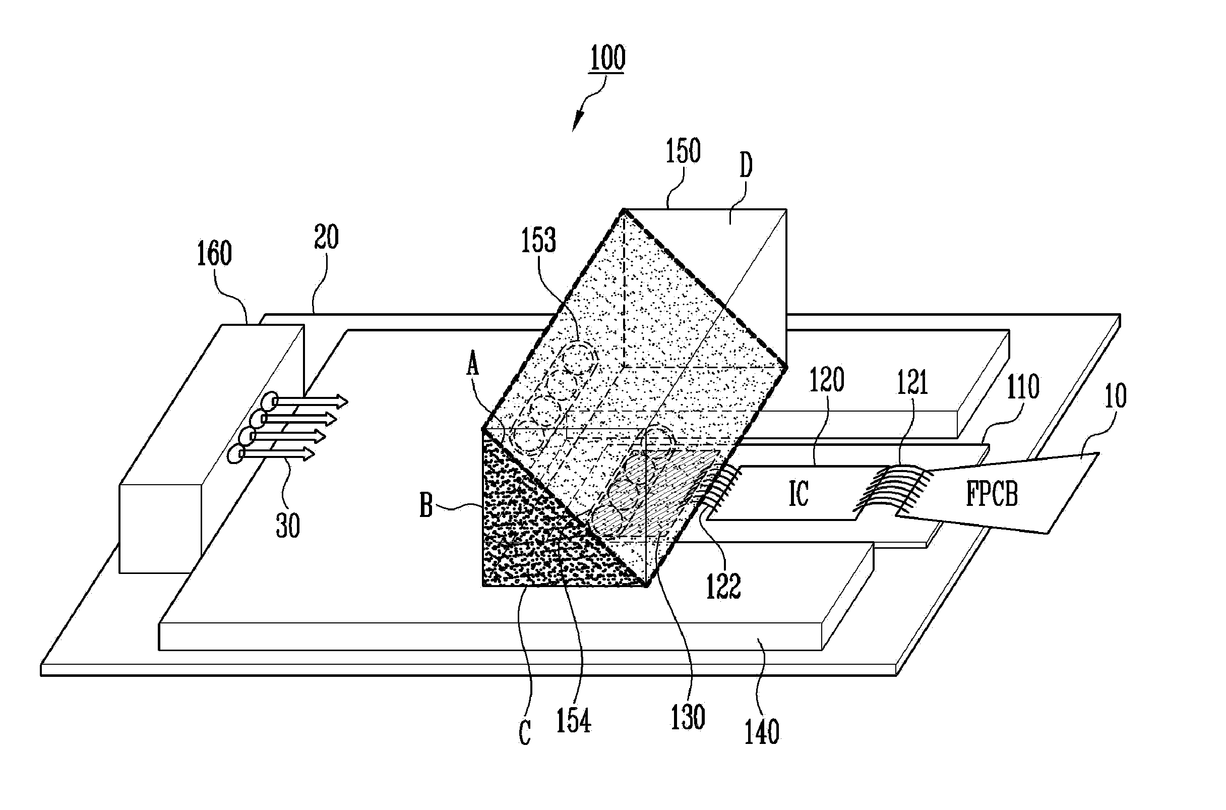
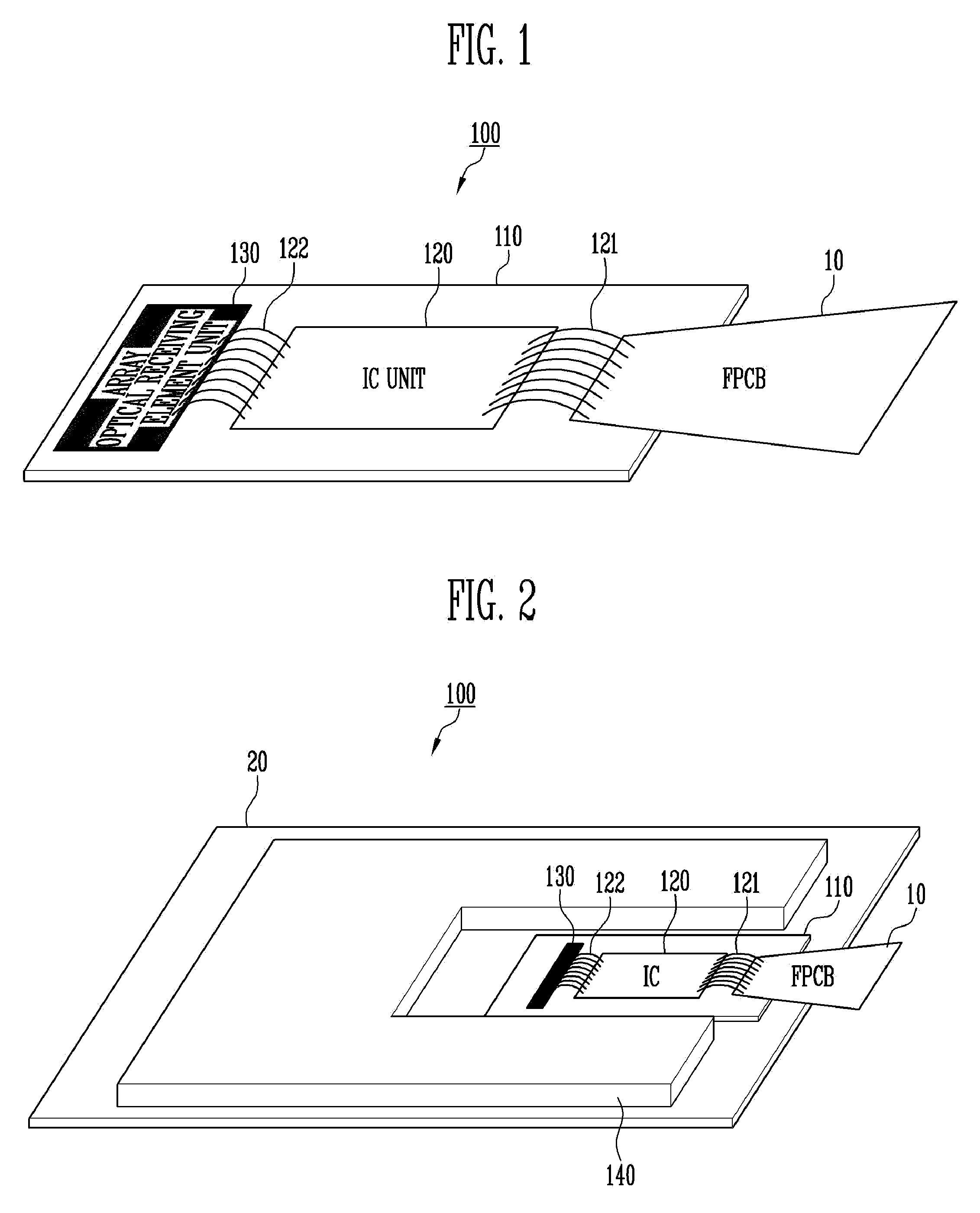
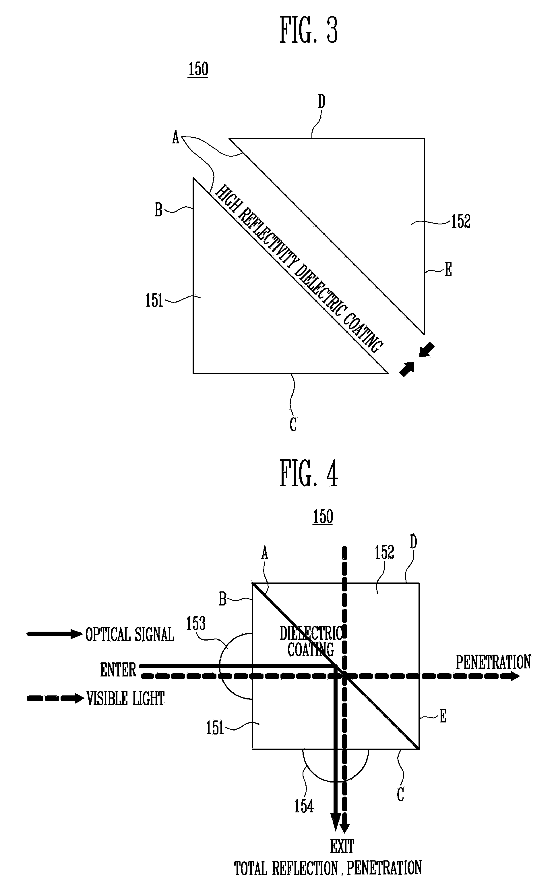
Provided herein is a multi-channel optical module that transmits or receives an optical signal of multi-channels and a manufacturing method thereof, the multi-channel optical module including a multi-channel optical fiber block configured to transmit an optical signal, a submount including an array optical receiving element unit configured to receive the optical signal; and a mirror unit arranged on a metal optical bench and configured to induce the optical signal transmitted from the multi-channel optical fiber block to the array optical receiving element unit, wherein for the inducement of the optical signal to the array optical receiving element unit, the mirror unit is passively aligned with the array optical receiving element unit, and the multi-channel optical fiber block is actively aligned with the mirror unit.

Description

CROSS-REFERENCE TO RELATED APPLICATION[0001]This application claims priority to and the benefit of Korean Patent Application No. 10-2014-0115621, filed on Sep. 1, 2014, in the Korean Intellectual Property Office, the entire contents of which are incorporated herein by reference in their entirety.BACKGROUND[0002]1. Field of Invention[0003]Various embodiments of the present disclosure relate to a multi-channel optical module and a manufacturing method thereof, and more particularly to a multi-channel optical module configured to transmit and / or receive an optical signal for optical communication of multiple channels (hereinafter referred to as an optical signal), and a manufacturing method thereof.[0004]2. Description of Related Art[0005]As various kinds of multimedia services are emerging these days, the need to exchange massive amounts of information has increased, which has caused an increase of amount of data being transmitted through a network. In response to such increased amoun...

Claims


Application Information

Patent Timeline
Patent Type & Authority Applications(United States)
IPC IPC(8): G02B6/42G02B6/32
CPCG02B6/4214G02B6/4207G02B6/32G02B6/4249G02B6/4257G02B6/4221
Inventor PARK, MI, RANKWON, O, KYUNKIM, HYUN, SOOJEONG, JONG, SOOL
Owner ELECTRONICS & TELECOMM RES INST
Learn More