Point cloud position data processing device, point cloud position data processing system, point cloud position data processing method, and program therefor

a technology of position data processing and data processing method, applied in the direction of image enhancement, instruments, and laser reradiation, to achieve the effect of efficient laser scanner calibration

Active Publication Date: 2016-03-03
KK TOPCON
View PDF3 Cites 20 Cited by
  • Summary
  • Abstract
  • Description
  • Claims
  • Application Information

AI Technical Summary

Benefits of technology

[0011]A fourth aspect of the present invention provides a storage medium storing a program to be read and executed by a computer, the program allowing the computer to receive reference point cloud position data, which is point cloud position data of an object to be measured, and to receive comparative laser scan data, which is obtained by scanning the object with laser light while a vehicle travels. The laser light is emitted from a laser scanner that is fixed on the vehicle and that is to be calibrated. The program also allows the computer to calculate comparative point cloud position data in a coordinate system of the reference point cloud position data from the comparative laser scan data based on a trajectory the laser scanner has traveled and to calculate exterior orientation parameters of the laser scanner based on a correspondence relationship between the reference point cloud position data and the comparative point cloud position data.
[0012]According to the present invention, the calibration of a laser scanner can be performed efficiently.

Problems solved by technology

However, complicated procedures are required for the calibration, and therefore, a technique for calibrating in a simpler manner is desired.

Method used


Image

  • Point cloud position data processing device, point cloud position data processing system, point cloud position data processing method, and program therefor
  • Point cloud position data processing device, point cloud position data processing system, point cloud position data processing method, and program therefor
  • Point cloud position data processing device, point cloud position data processing system, point cloud position data processing method, and program therefor

Examples


example of processing

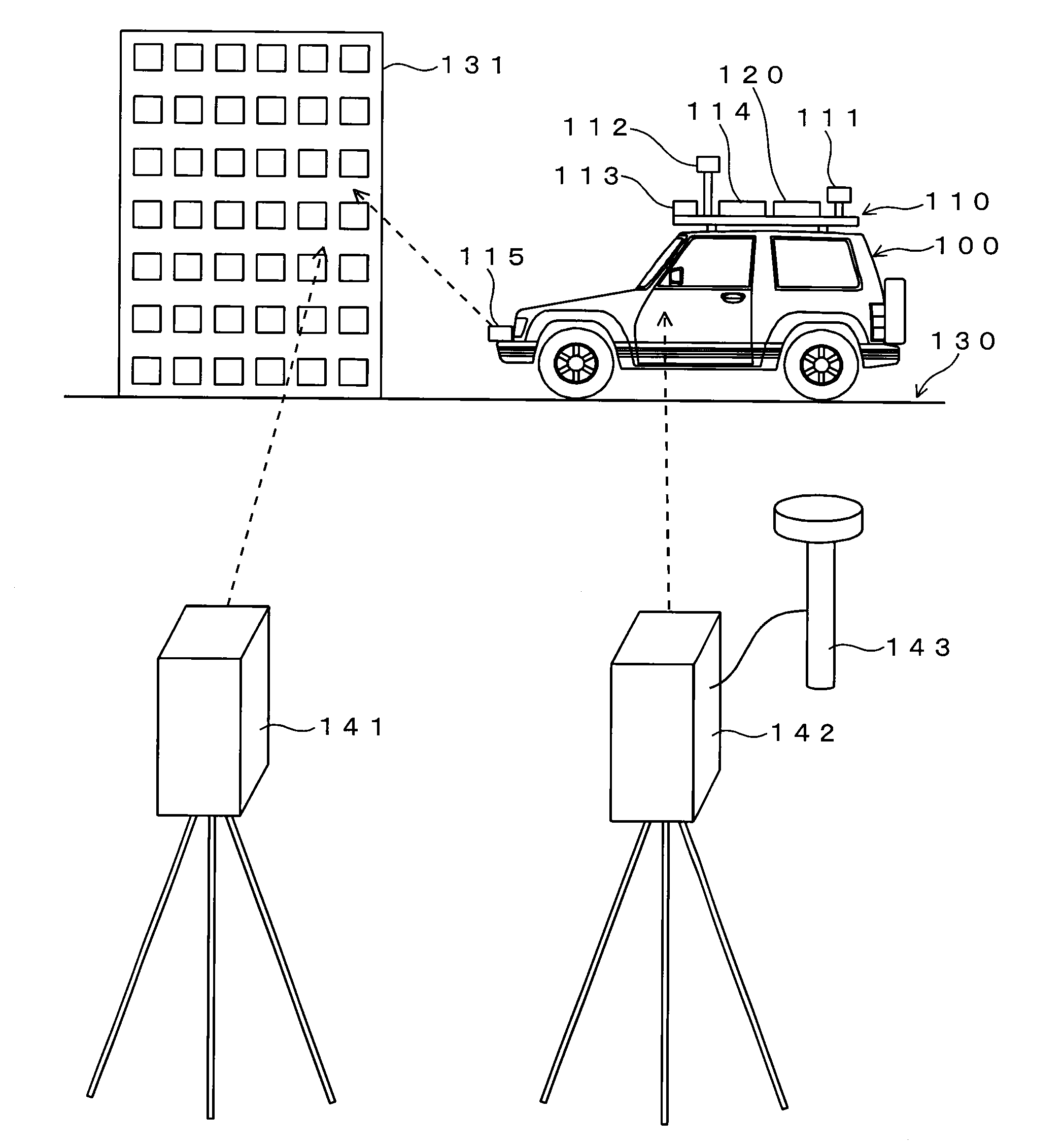
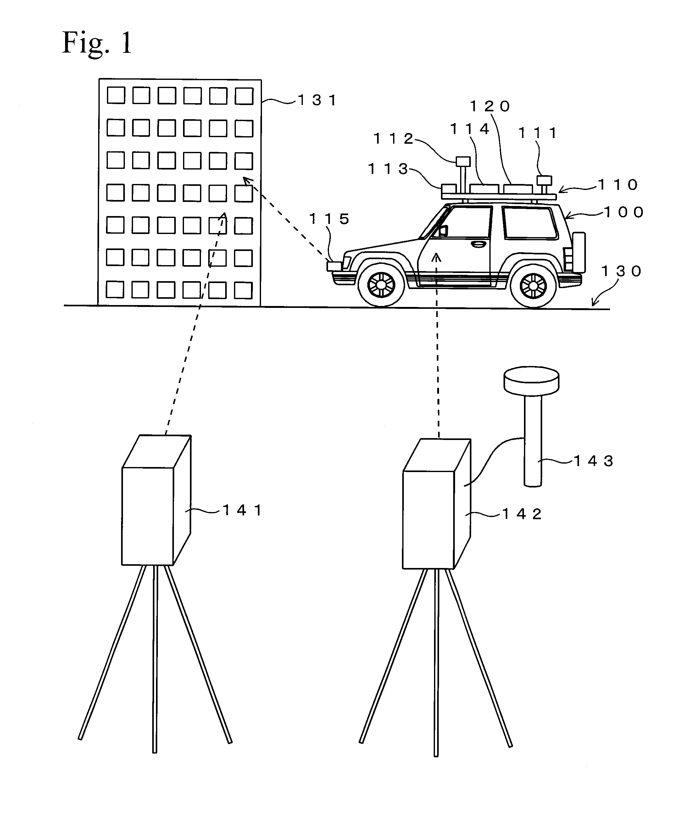
[0082]An example of the processing for calculating the exterior orientation parameters of the laser scanner 115 will be described hereinafter. FIG. 5 is a flow chart showing an outline of the processing. First, the vehicle 100 equipped with the measuring system 110 and the laser scanner 115 is prepared. In this stage, the position of the GNSS unit 111 on the measuring system 110, the exterior orientation parameters of the panoramic camera 112 and the fixed direction camera 113, and the position and the attitude of the IMU 114 are measured and are already known. In addition, the laser scanner 115 is mounted on the vehicle 100 at a position freely selected by a user, and the approximate position and the approximate attitude thereof are already known, but accurate exterior orientation parameters (position and attitude with respect to the IMU 114) are not determined.

[0083]After the vehicle 100 is prepared, a calibration course 130 is set (step S101). As the calibration course 130, a lin...


PUM


Abstract

A technique for performing calibration of a laser scanner efficiently is provided. Point cloud position data of a building 131 is obtained by a laser scanner 141 in which exterior orientation parameters are already known. On the other hand, the building 131 is scanned by a laser scanner 115 while a vehicle 100 travels, and point cloud position data of the building 131 measured by the laser scanner 115 is obtained based on a trajectory the vehicle 100 has traveled. Then, exterior orientation parameters of the laser scanner 115 are calculated based on a correspondence relationship between these two point cloud position data.

Description

BACKGROUND OF THE INVENTION[0001]1. Technical Field[0002]The present invention relates to a technique for calibrating a laser scanner.[0003]2. Background Art[0004]Laser scanners emit laser light on objects to be measured and obtain point cloud position data based on light reflected by the objects. The point cloud position data contains data of three-dimensional coordinates of measured points obtained in dot-like shapes, and a three-dimensional model (for example, a three-dimensional CAD data) of the object can be obtained based on the point cloud position data. For example, when a vehicle, which is equipped with an IMU (Inertial Measurement Unit) and a laser scanner, travels, point cloud position data of the surrounding is obtained by the laser scanner while the location and the attitude of the vehicle are measured by the IMU, whereby a three-dimensional model of the surrounding conditions of the traveled route can be obtained (for example, refer to Japanese Unexamined Patent Applic...

Claims


Application Information

Patent Timeline
Patent Type & Authority Applications(United States)
IPC IPC(8): G06T7/00G01S7/497G01S17/42G01S17/58G01S17/86G01S17/89G06T17/10
CPCG06T2210/56G06T2207/10028G06T17/10G06T7/0057G01S17/58G01S7/497G01S7/4972G01S17/023G01S17/42G01S17/89G01S19/00G01S7/4808G06T2215/16G01S5/16G06T7/521G01S17/86G06T7/246
Inventor SASAKI, YOUITO, TADAYUKIOGAWA, KAZUHIRO
Owner KK TOPCON
Why Eureka
Try Eureka