
Method and apparatus for supplying power to a radio frequency power amplifier

a radio frequency power amplifier and power supply technology, applied in the field of supply modulators, can solve the problems of difficulty in meeting all of the above-described requirements, low power efficiency in peak power and back-off power regions, and the loss of rf pa, etc., and achieve the effect of improving the respective peak power efficiency

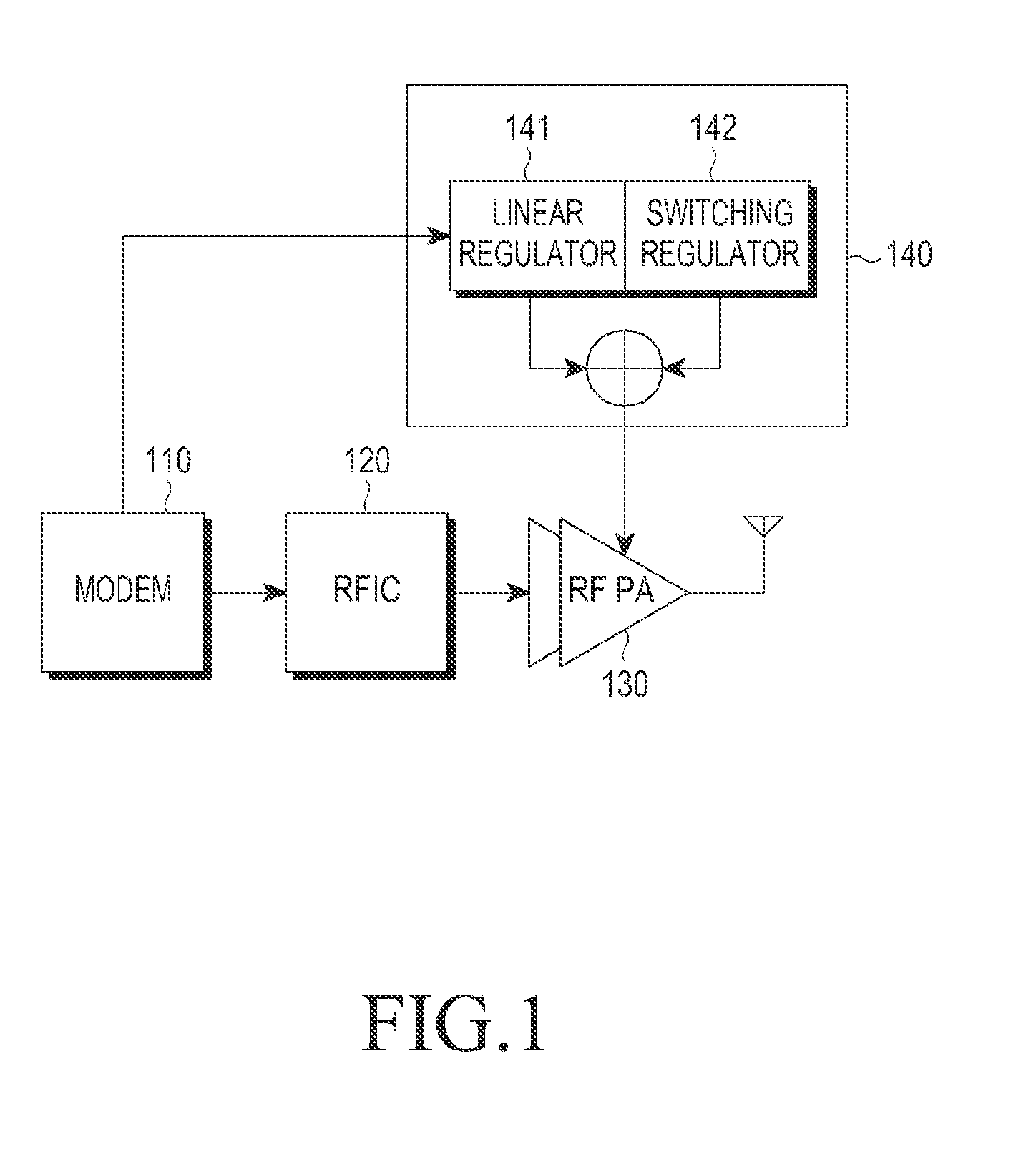
Active Publication Date: 2016-03-03
SAMSUNG ELECTRONICS CO LTD
View PDF4 Cites 37 Cited by
  • Summary
  • Abstract
  • Description
  • Claims
  • Application Information

AI Technical Summary

Benefits of technology

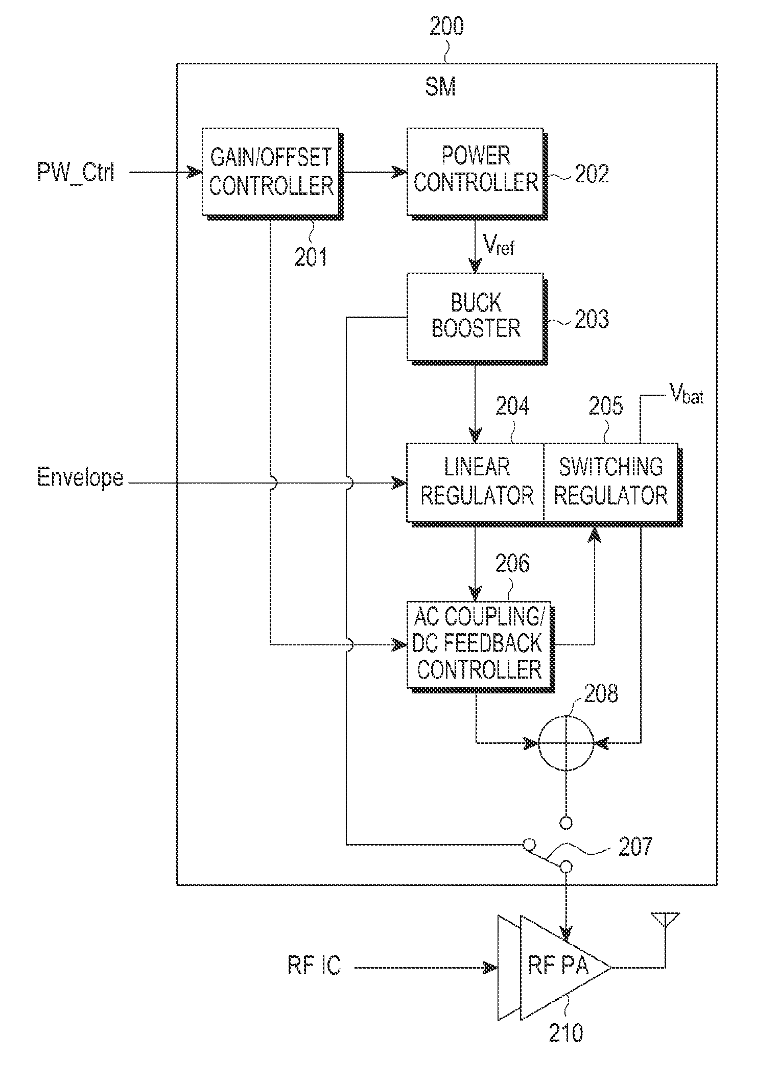
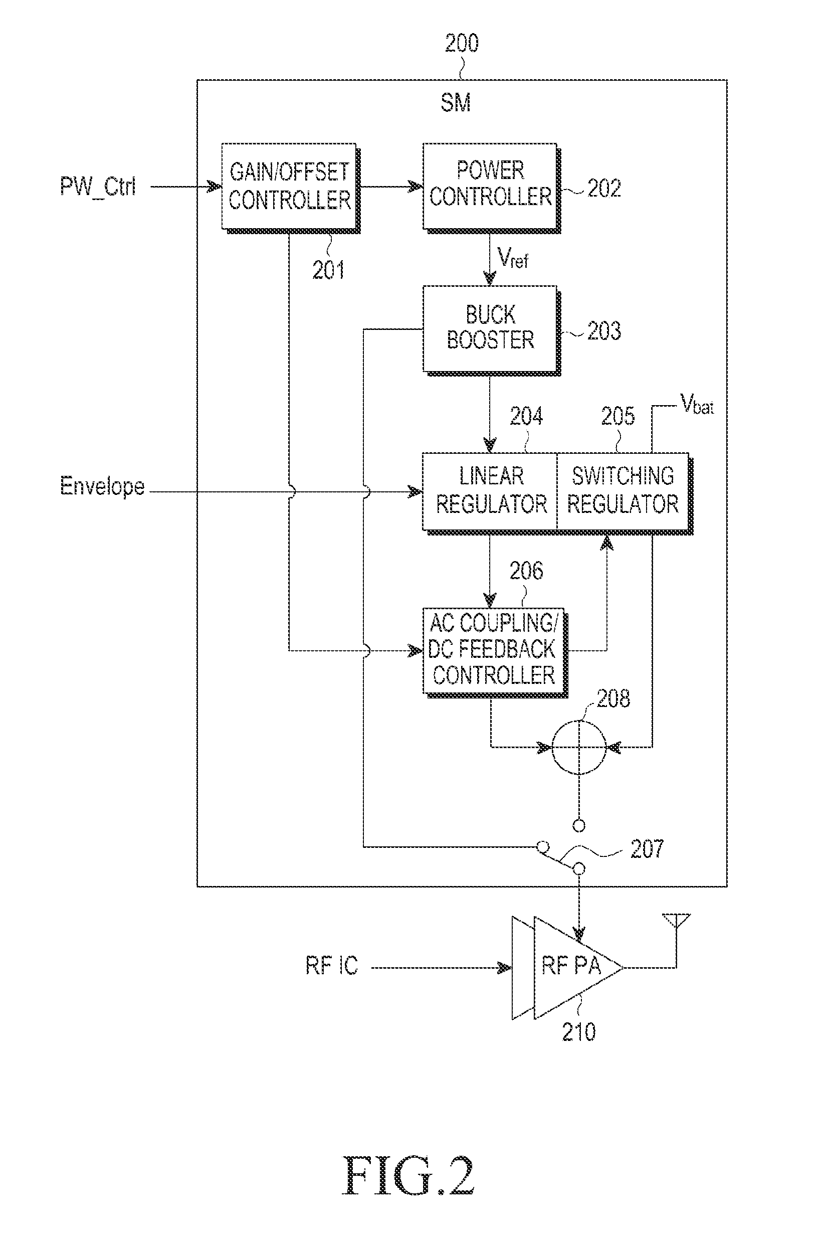
The present invention provides a way to improve the power conversion efficiency of a power amplifier in both peak power and back-off power modes. This is achieved by using an adaptive control system that adjusts the envelope shape table and the supply voltage of a power amplifier using an SM. The SM includes a power controller, a buck booster, a combiner, and a switch that can change the operating mode of the SM to an ET mode or an APT mode based on whether the second end is connected to the buck booster or the combiner. This results in better power conversion efficiency for the power amplifier.

Problems solved by technology

The RF / analog output amplifier required in terminals for RF communication has procedural and circuit-structural limitations that make it difficult to satisfy all of the above-described requirements.
Since high PAPR characteristics require a high 1 dB gain compression point (P1 dB) and saturated power of the RF PA, all existing RF PAs operating with limited fixed supplies, such as, for example, batteries, have low power efficiency in peak power and back-off power regions.
However, when the APT technology is applied, the fixed supply voltage is unable to instantaneously catch up with an envelope signal, and thus, the RF PA suffers additional power loss.
However, output voltage shaping by power control requires an increase in the complexity of the operation of the communication system and an RF driver.
In other words, there is an efficiency loss of a linear amplifier in proportion to a ratio of output voltage to fixed supply voltage, which reduces the entire efficiency of the SM due to the back-off power.

Method used


Image

  • Method and apparatus for supplying power to a radio frequency power amplifier
  • Method and apparatus for supplying power to a radio frequency power amplifier
  • Method and apparatus for supplying power to a radio frequency power amplifier

Examples


Embodiment Construction

[0033]Embodiments are described in detail with reference to the accompanying drawings. The same or similar components may be designated by the same or similar reference numerals although they are illustrated in different drawings. Detailed descriptions of constructions or processes known in the art may be omitted to avoid obscuring the subject matter of the present invention.

[0034]The terms “include”, “comprise”, and their derivatives, as used herein, are defined as non-exclusive inclusion. The term “and / or”, as used herein, includes any and all combinations of one or more of the associated listed items. The phrases “associated with”, “associated therewith”, and / or their derivatives, as used herein, are substantially equivalent to ‘include’, ‘be included within’, ‘interconnect with’, ‘contain’, ‘be contained within’, ‘connect to or with’, ‘couple to or with’, ‘be communicable with’, ‘cooperate with’, ‘interleave’, ‘juxtapose’, ‘be proximate to’, ‘be bound to or with’, ‘have’, ‘have ...


PUM


Abstract

A method and a supply modulator (SM) are provided for supplying power from a wireless transmitter to a radio frequency (RF) power amplifier. A power control signal input from a modem is received. A reference voltage is determined. An operating mode of the SM is changed by controlling a level of the reference voltage. A voltage is determined based on the level of a reference voltage. When the operating mode of the SM is an ET mode, a first output signal from a linear regulator and a second output signal from a switching regulator are combined to obtain a combined result, and the combined result is output. The first output signal is based on the voltage. When the operating mode of the SM is an APT mode, the voltage based on the reference voltage is output.

Description

PRIORITY[0001]This application claims priority under 35 U.S.C. §119(e) to a U.S. provisional application filed on Sep. 2, 2014 in the U.S. Patent and Trademark Office and assigned Ser. No. 62 / 044,725, and under 35 U.S.C. §119(a) to a Korean patent application filed on Apr. 30, 2015 in the Korean Intellectual Property Office and assigned Serial No. 10-2015-0061379, the contents of which are incorporated herein by reference.BACKGROUND[0002]1. Field of the Disclosure[0003]The present disclosure relates generally to a supply modulator (SM) used for radio transmitters in communication systems.[0004]2. Description of Related Art[0005]Battery power consumption is considered to be a very important aspect of applications for radio communication terminals. Thus, a highly efficient radio frequency (RF) / analog output amplifier is required for long battery use. With the evolution from 2G to 3G / 4G, highly efficient characteristics are required with a high peak-to-average power ratio (PAPR). Furth...

Claims


Application Information

Patent Timeline
IPC IPC(8): H03F1/02H03F3/19H03F3/21H03G3/30H04B1/04
CPCH03F1/0227H03F3/19H03F3/21H03F2200/451H04B1/04H03F2200/102H03G3/3042H03F1/0222H03F1/3223H03F3/211H03F3/24H03F3/245H03F3/72H03F2200/375H03F2200/411H03F2200/432H03F2200/78H03F2203/7227H04B1/0475H04B2001/0441
Inventor LEE, SUNG-JUNPAEK, JI-SEONLEE, SEUNG-CHULYOUN, YONG-SIKJUNG, JUN-HEECHO, THOMAS, BYUNGHAKHAN, SANG-WOOK
Owner SAMSUNG ELECTRONICS CO LTD
Learn More