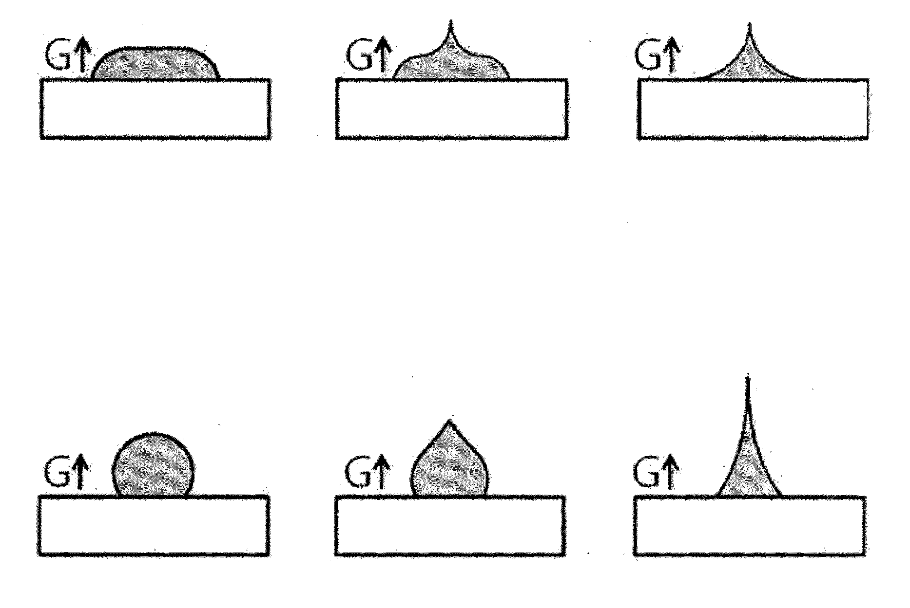
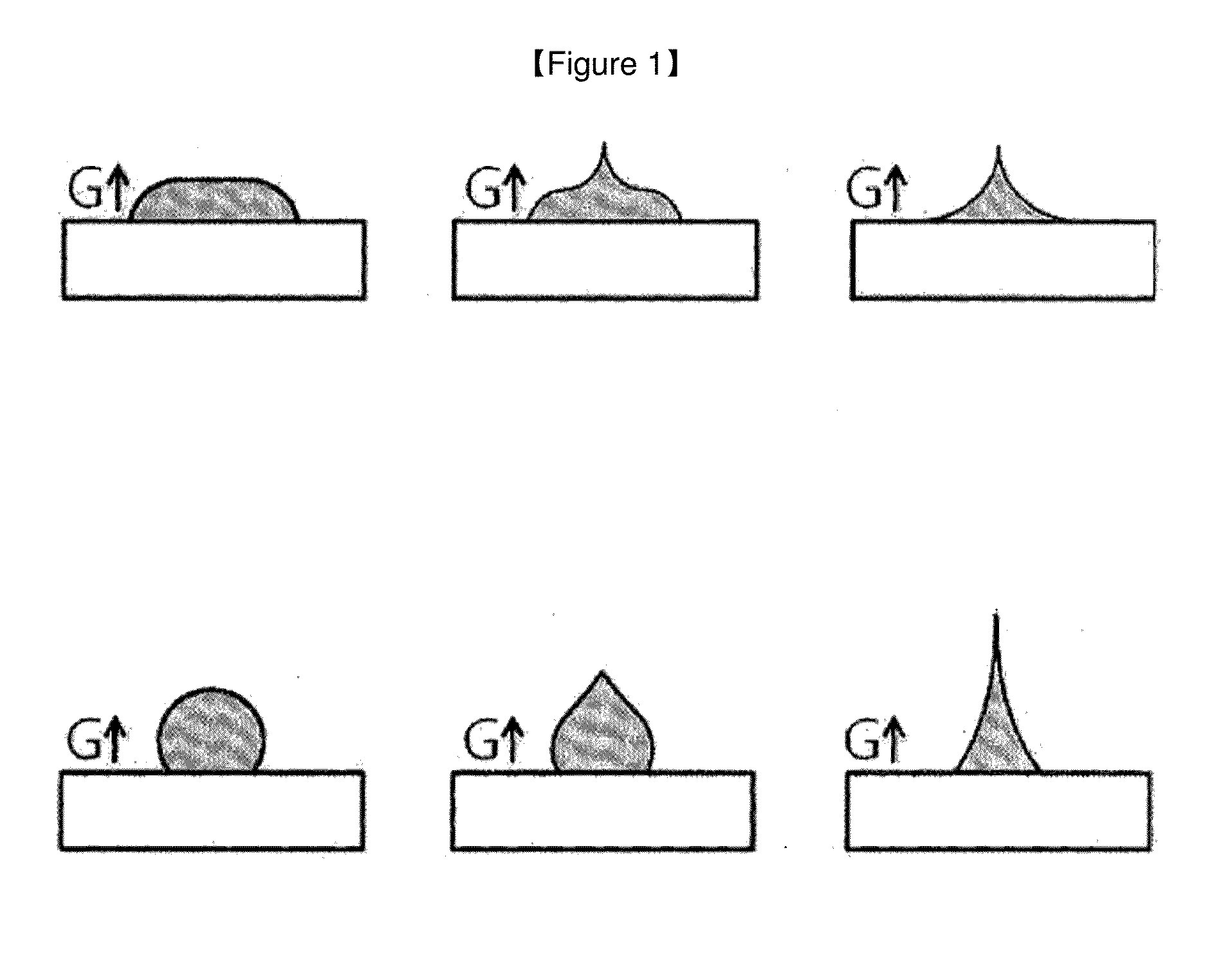
Method for manufacturing microstructure using centrifugal force and microstructure manufactured by same
a technology of centrifugal force and microstructure, which is applied in the field of manufacturing a microstructure using centrifugal force and the same microstructure, can solve the problems of ineffective delivery of numerous drugs by the above administration method, inability to effectively diffuse drugs, and inability to effectively deliver drugs. , to achieve the effect of easy destruction or deformation, rapid and simple process, and high yield
- Summary
- Abstract
- Description
- Claims
- Application Information
AI Technical Summary
Benefits of technology
Problems solved by technology
Method used
Image
Examples
embodiments
Embodiment 1
Manufacture of Microstructure with High Aspect Ratio Using Centrifugal Force
[0150]After coating carboxymethylcellulose (Sigma-Aldrich, Inc.) to a polystyrene substrate (SPL Life Science), a viscous solution drop of 40 wt % hyaluronic acid (Soliance) was formed. Then, the substrate was mounted on a centrifuge (Beckman coulter), the centrifuge was accelerated at 5 g / s, and was operated for three minutes at a gravitational acceleration of 900 g. Then, the centrifuge was decelerated at a velocity of 9 g / s. Through the centrifugal force application process, a microstructure with a high aspect ratio was manufactured (reference: FIG. 19) having an effective length of 1,500 μm, a top portion diameter of 45 μm, and a bottom portion diameter of 300 μm.
[0151]Meanwhile, a separate process of solidifying the manufactured microstructure was not required, and the solidifying simultaneously occurred in the process of applying the centrifugal force.
[0152]Consequently, it can be realized ...
embodiment 2
Manufacture of Microstructure Using Two Substrates (Inner and Outer Substrates)
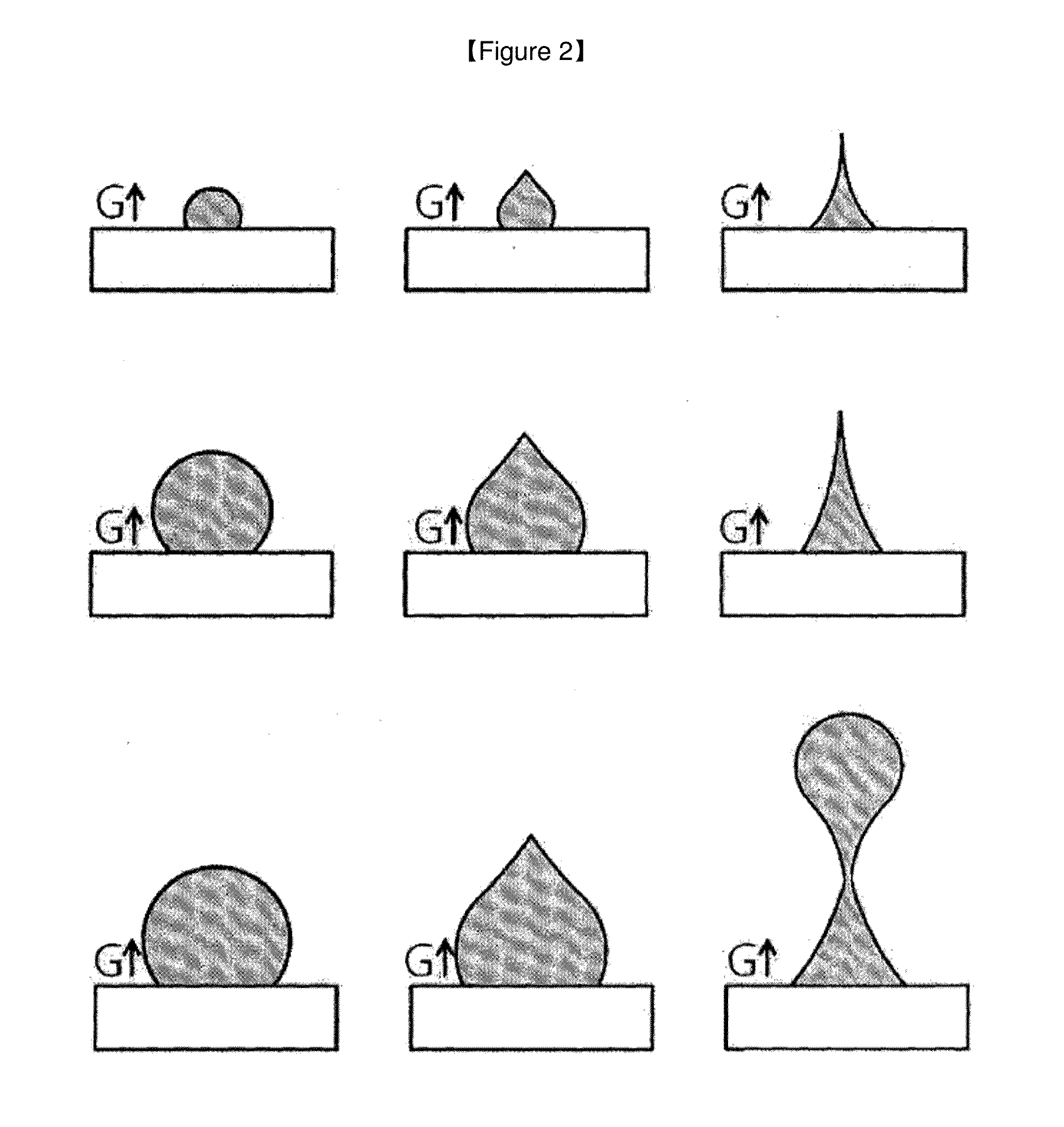
[0153]After discharging 40% (w / v) of 29 kDa hyaluronic acid solution on an aluminum substrate, which is a lower substrate, for 0.220 seconds at a pressure of 0.200 MPa using a dispenser (MUSASHI engineering, ML-5000XII) and forming a solution drop, a centrifuge (Hanil science industrial, Combi 514R) was used to rotate the solution drop between two aluminum substrates, which are respectively the lower substrate and an upper substrate, spaced apart by 1 mm, by a centrifugal force of 500 g for 30 seconds, thereby forming a microstructure (reference: FIG. 20). A left-side figure of FIG. 20 is a microstructure formed on the lower substrate (inner substrate), and a right-side figure of FIG. 20 is a microstructure formed on the upper substrate (outer substrate).
embodiment 3
Check Microstructure Formation Through Electron Microscope
[0154]The microstructure that was manufactured by Embodiment 2 was observed with an electron microscope (Field Emission Scanning Electron Microscope, JSM-7001F, JEOL Ltd., Japan). The microstructures were formed on both the upper substrate and the lower substrate (reference: FIG. 21).
PUM
| Property | Measurement | Unit |
|---|---|---|
| Time | aaaaa | aaaaa |
| Force | aaaaa | aaaaa |
| Centrifugal force | aaaaa | aaaaa |
Abstract
Description
Claims
Application Information
 - R&D
- Intellectual Property
- Life Sciences
- Materials
- Tech Scout
- Unparalleled Data Quality
- Higher Quality Content
- 60% Fewer Hallucinations
Browse by: Latest US Patents, China's latest patents, Technical Efficacy Thesaurus, Application Domain, Technology Topic, Popular Technical Reports.
© 2025 PatSnap. All rights reserved.Legal|Privacy policy|Modern Slavery Act Transparency Statement|Sitemap|About US| Contact US: help@patsnap.com


