Conductive line and routing structure for the same
a technology of conductive lines and routing structures, which is applied in the direction of insulated conductors, cables, conductors, etc., can solve the problems of reducing the diameter of shield pipes, and achieve the effect of reducing the diameter, high bendability, and small bending exten
- Summary
- Abstract
- Description
- Claims
- Application Information
AI Technical Summary
Benefits of technology
Problems solved by technology
Method used
Image

Examples
first embodiment
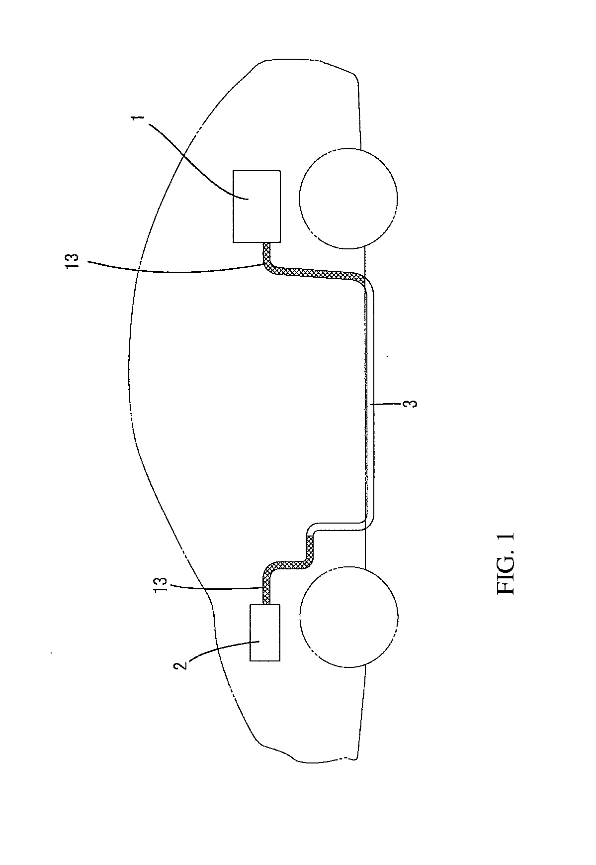
[0030]A conductive line according to the present embodiment is applied to a hybrid vehicle. A battery 1, which has been mounted in the rear side of a vehicle, is connected to an inverter 2, which has been provided inside an engine room, via a wire harness WH As shown in FIG. 4, in the case of the present embodiment, the wire harness WH is constituted by three conductive lines L.
[0031]The wire harness WH is collectively inserted into a shield pipe 3 that has been arranged underneath the vehicle. More specifically, the rear end side of the shield pipe 3 is introduced to the rear side of the cabin, and a metallic braided portion 13 (to be described later) is interposed between the battery 1 and the shield pipe 3. An intermediate portion of the shield pipe 3 extends in an approximately horizontal fashion along the front-rear direction underneath the vehicle. The front end side bends upwards and is introduced to the engine room, and extends out toward the inverter 2.
[0032]The shield pipe...
second embodiment
[0048]FIG. 5 shows a second embodiment of the present invention.
[0049]In the first embodiment, the junction portions between the single-core line electrical lines and the stranded electrical lines of the conductor lines L are at positions aligned with respect to the front-rear direction (see FIG. 4), but in the second embodiment, these junction portions are successively shifted the front-rear direction.
[0050]The connection of the single-core line electrical line 4 and the stranded electrical line 5 is performed after the single-core line electrical line 4 has been inserted into the shield pipe 3, and in cases of this task order, if the junction portion of the conductive line L were to be shifted front-end, interference between a welding machine and the conductive line L is easily avoided, and the welding task can be smoothly performed. Other configurations are similar to the above embodiment, and thus can exhibit similar effects.
third embodiment
[0051]FIG. 6 shows a third embodiment of the present invention.
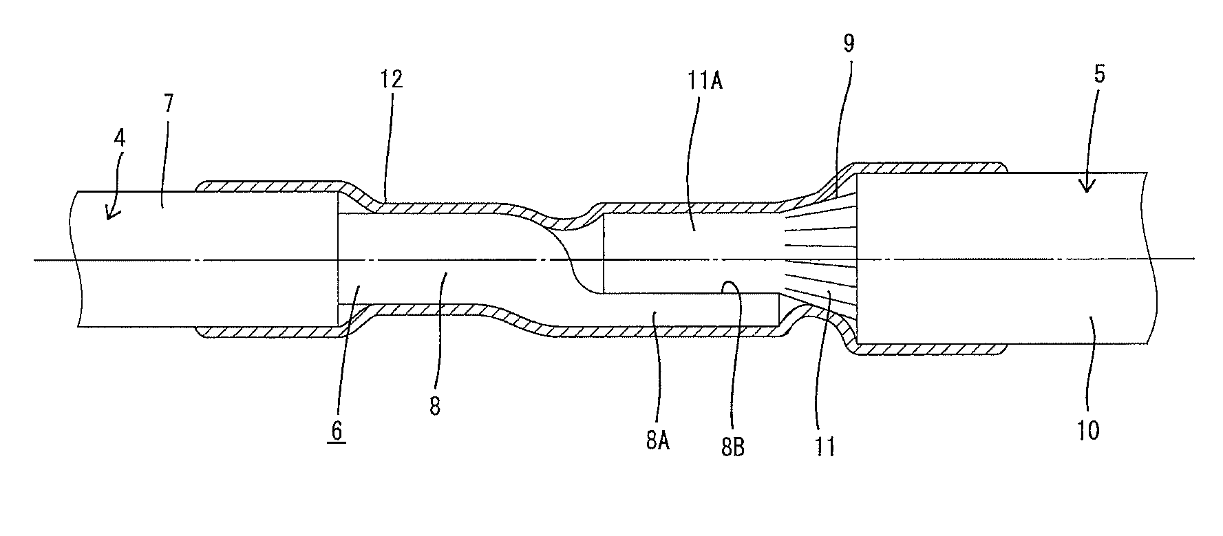
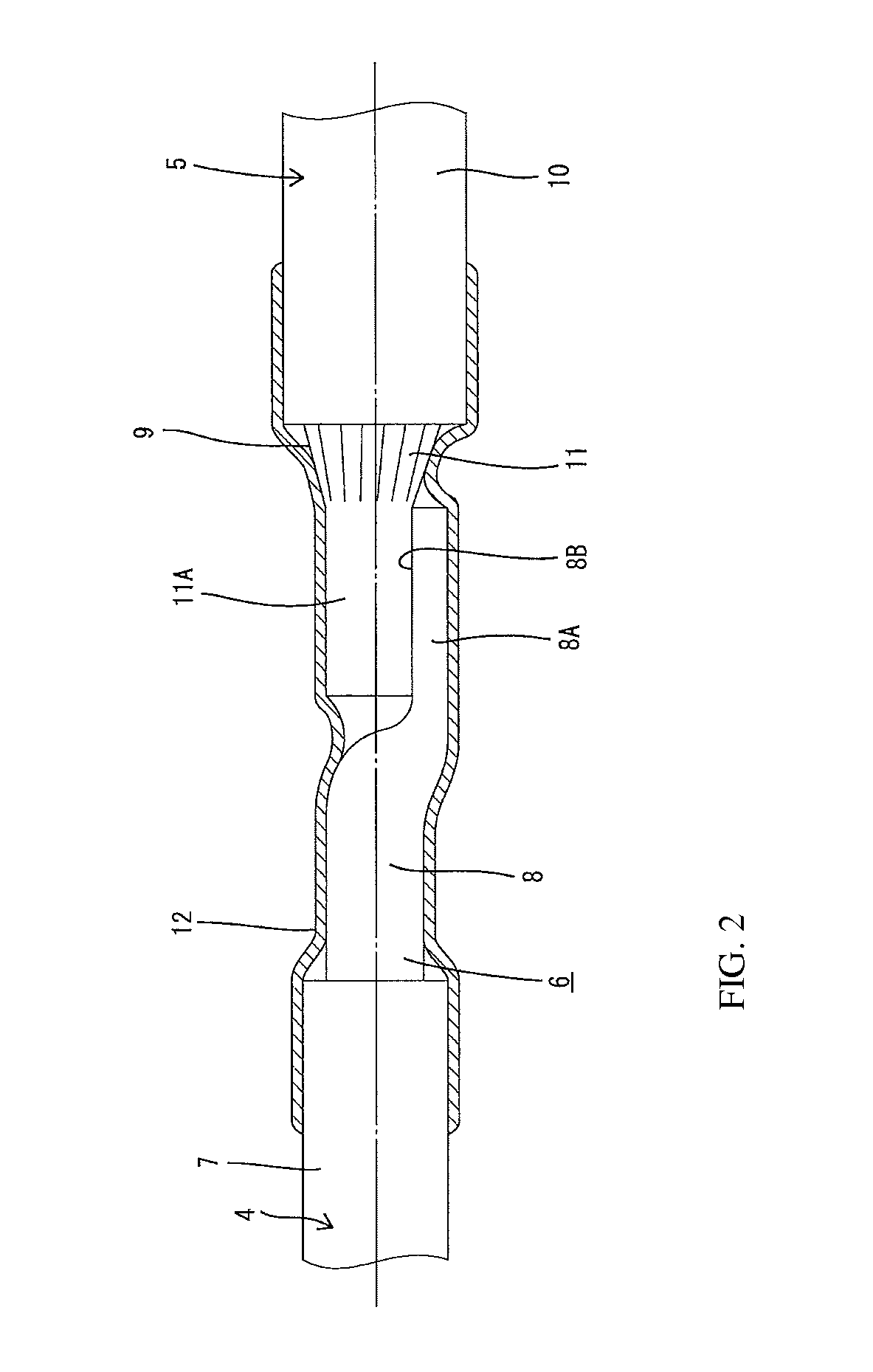
[0052]In the first and second embodiment, the collapsed portion 8A and the connection block portion 11A are connected so as to overlap in the diameter direction, but in the third embodiment, end surfaces of the conductor exposed portion 8 and the individual wire exposed portion 11 are butted against each other coaxially, and the abutting end surfaces are fused together. In this case, the individual wires 9 in the tip portion of the individual wire exposed portion 11 are welded into a block, similarly to the connection block portion 11A.
[0053]In the third embodiment configured as described above, the junction portion does not bulge out from the general portion of the electrical line in the diameter direction, and therefore reduction of the diameter of the shield pipe 3, and excessive interference with the heat shrink tube 12 can be avoided.
[0054]Other configurations are similar to the first and second embodiments, and thu...
PUM
 Abstract
Description
Claims
Application Information
 - R&D
- Intellectual Property
- Life Sciences
- Materials
- Tech Scout
- Unparalleled Data Quality
- Higher Quality Content
- 60% Fewer Hallucinations
Browse by: Latest US Patents, China's latest patents, Technical Efficacy Thesaurus, Application Domain, Technology Topic, Popular Technical Reports.
© 2025 PatSnap. All rights reserved.Legal|Privacy policy|Modern Slavery Act Transparency Statement|Sitemap|About US| Contact US: help@patsnap.com