

Grid tied, real time adaptive, distributed intermittent power
a distributed, intermittent power technology, applied in emergency power supply arrangements, instruments, computer control, etc., can solve the problems of unpredictable rapid fluctuations in electrical power generation, uncommercially viable solutions, and restrictions or even forbidding additional connections, so as to reduce the overall cost of these systems for customers and storage capacity.
- Summary
- Abstract
- Description
- Claims
- Application Information
AI Technical Summary
Benefits of technology
Problems solved by technology
Method used
Image

Examples
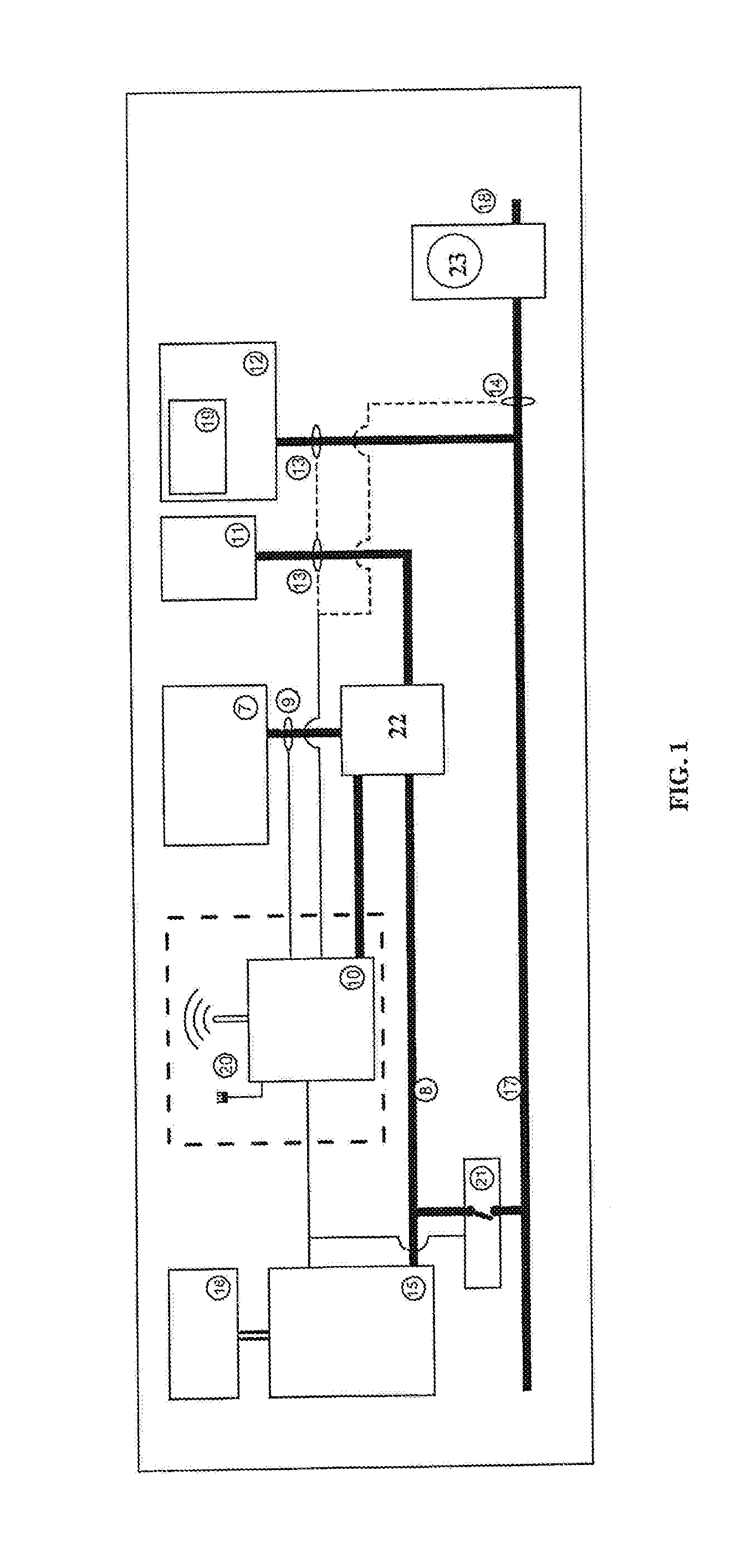
first embodiment
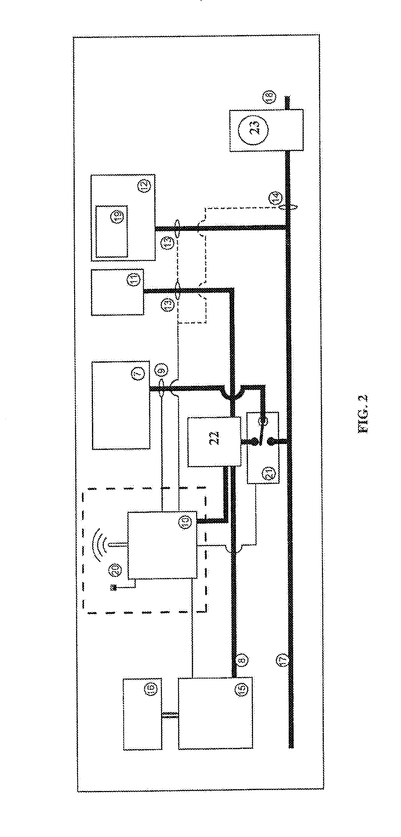
[0059]Referring to FIG. 2, shown is a second presently preferred embodiment of the invention. This embodiment functions like the first embodiment, except that the micro grid is created when the isolating switch 21 is opened and the intermittent power generation system 7 is connected to the micro grid connected circuit 8 at the electric distribution box 22. When the intermediate circuit 18 is on-line and micro grid connected circuit 8 is not necessary, isolating switch 21 is preferably closed and the intermittent power generation system 7 is connected to the customer circuit 17.
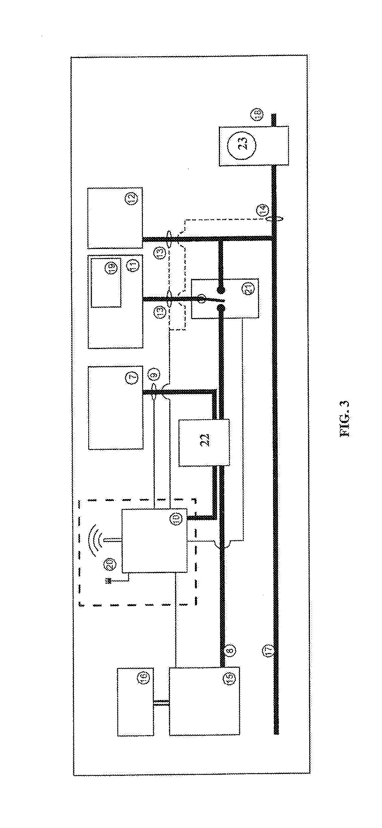
[0060]Referring to FIG. 3, shown is a third presently preferred embodiment of the invention comprising an intermittent power generation system 7 that delivers intermittent power through the electric distribution box 22 to the micro grid connected circuit 8. The energy management controller 10 continually measures power produced by the intermittent power generation system 7 at 9 in real time. Other electric loa...
fourth embodiment
[0064]Referring to FIG. 4, shown is a fourth presently preferred embodiment of the invention. The fourth embodiment does not contain a separate micro grid connected circuit with the ability to isolate that micro grid circuit when the intermediate circuit is off-line. It also does not contain a charger / inverter or storage device.
[0065]Instead, it preferably comprises an intermittent power generation system 7 that delivers unpredictable and varying amounts of power to the customer circuit 17 and other electric loads 12 that draw unpredictable and varying amounts of power from the customer circuit 17. The controller 10 preferably continually measures power consumed by loads at 13, and power exported or imported to and from the intermediate circuit at the point of common coupling 14, separating out the intermittent power produced by the intermittent power generation system 7 at 9, to determine actual load in real time.
[0066]The energy management controller 10 preferably acts according t...
fifth embodiment
[0068]Referring to FIG. 5, shown is a fifth presently preferred embodiment of the invention. The fifth embodiment does not contain a separate micro grid connected circuit, an storage device, or an intermittent power generation system. It comprises electric loads 12 that draw unpredictable and varying amounts of power from the customer circuit 17, and an energy management controller 10 that continually measures power consumed by the electric loads at 13, or power exported or imported to and from the intermediate circuit at the point of common coupling 14 to determine actual load.
[0069]The energy management controller 10 acts according to updatable utility (or other grid participant) rules in real time in response to its measurement of actual load to manage power entering the intermediate circuit 18 by connecting controlled loads 19 to the customer circuit 17, thereby increasing load, or disconnecting them from the customer circuit 17, thereby decreasing load, to achieve the utility's...
PUM
 Abstract
Description
Claims
Application Information