Differential capacitive antenna ports coexistence in wireless capacitive signal reception and transmission systems and/or wireless capacitive power supply transmission systems

a capacitive and antenna port technology, applied in the field of electrical communication systems, can solve the problems of higher channel error, inability and the actual loss of connection, so as to solve the complex task of creating a capacitive interface on the capacitive channel (connector or antenna port) and thus on the system

Active Publication Date: 2016-03-10
BOSENKO ROSTYSLAV VOLODYMYROVYCH
View PDF5 Cites 4 Cited by
  • Summary
  • Abstract
  • Description
  • Claims
  • Application Information

AI Technical Summary

Benefits of technology

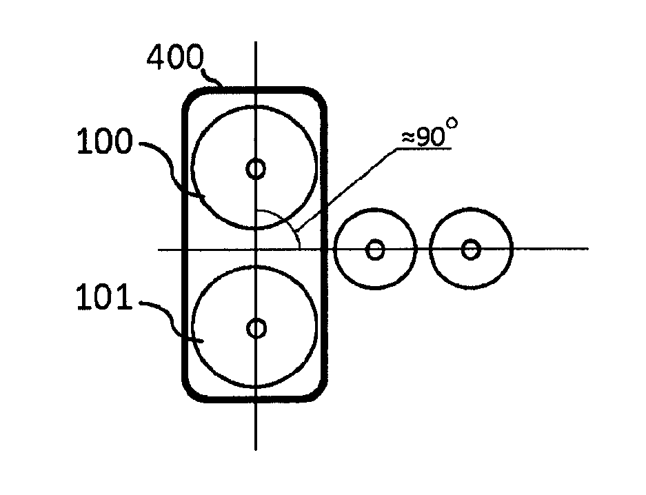
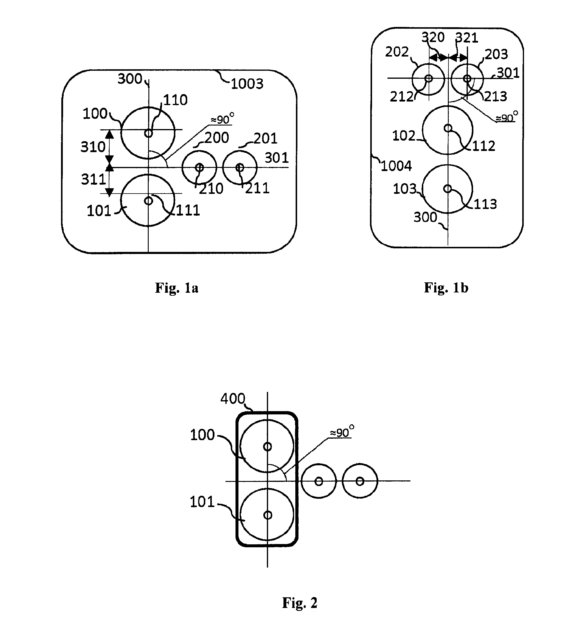
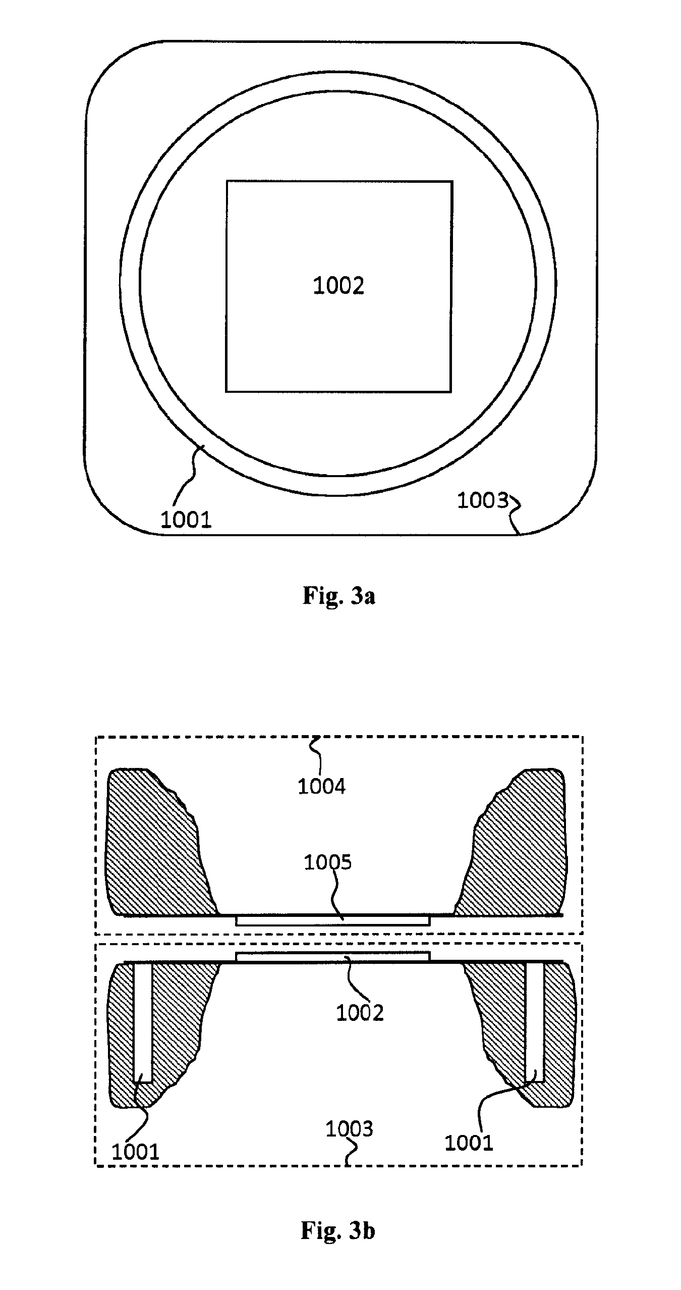
[0007]The aim of the claimed invention is to design such antenna ports that will ensure the coexistence in the same antenna unit (port) of terminals for receiving apparatuses, transmitting apparatuses and apparatuses for wireless capacitive power supply reception and transmission and compensation of parasitic

Problems solved by technology

A significant drawback of known capacitive systems, methods and devices is that they do not solve the complex task of creating a capacitive interface that can integrate in one solution all the capabilities that are similar to the capabilities of modern high-speed wire serial differential interfaces with power supply transmission line.
One of the known issues in this sense is the parasitic inte

Method used


Image

  • Differential capacitive antenna ports coexistence in wireless capacitive signal reception and transmission systems and/or wireless capacitive power supply transmission systems
  • Differential capacitive antenna ports coexistence in wireless capacitive signal reception and transmission systems and/or wireless capacitive power supply transmission systems
  • Differential capacitive antenna ports coexistence in wireless capacitive signal reception and transmission systems and/or wireless capacitive power supply transmission systems

Examples


second embodiment

[0042]In the present invention, a differential capacitive antenna port for the wireless capacitive signal reception and transmission with the channel of wireless power supply transmission, where the layout of the terminals on its working surface 1013 is shown in FIG. 4a, comprises the receiving terminals 500 and 501, the transmitting terminals 600 and 601 and electrical energy transmitting terminals 700 and 701. In this case, the points 610 and 611 are the input feed point for signals from the antenna port inputs to the transmitting terminals, and the points 510 and 511 are the output feed points for signals from the receiving terminals to the outputs of the antenna port, and points 710 and 711 are input feed points for signals to the energy transmitting terminals.

[0043]Provided that, the elimination of electric fields parasitic influence radiated by the transmitting terminals 600, 601, 700, and 701 to the receiving terminals 500 and 501, is achieved by the respective relative posit...

third embodiment

[0054]In the present invention, a differential capacitive antenna port for a wireless capacitive signal reception and transmission with the channel of wireless power supply reception and transmission, where the layout of the terminals on its working surface 1023 is shown in FIG. 6, comprises the receiving terminals 500 and 501, the transmitting terminals 600 and 601, and two pairs of electrical energy transmitting terminals 700 and 701, 750 and 751. In this case, the points 610 and 611 are the input feed point for signals from the antenna port inputs to the transmitting terminals, and points 510 and 511 are the output feed point for signals from the receiving terminals to the outputs of the antenna port, and points 710 and 711, 760 and 761 are input feed points for signals to the energy transmitting terminals. 900 is the center of symmetry.

[0055]Provided that, the elimination of electric fields parasitic influence radiated by the transmitting terminals 600, 601, 700, 701, 750 and 75...


PUM


Abstract

Disclosed are antenna ports for high-speed, short-range, capacitive wireless devices that can be used for stream data and power supply transmission between two adjacent electronic devices, modules, etc. In various embodiments, differential capacitive antenna ports for the wireless capacitive signal reception and transmission include a capacitive transmission port configured to generate electric fields that represent transmitted signals with at least one pair of transmitting terminals, with conductive working surfaces connected to the port inputs at the input feed points, and a capacitive reception port configured to detect electric fields that represent transmitted signals with at least one pair of receiving terminals, with conductive working surfaces connected to the port outputs at the output feed points.

Description

FIELD OF THE DISCLOSURE [0001]The invention relates to the field of electronic communication systems. More specifically, the invention relates to antenna devices (ports) for high-speed, short-range, capacitive wireless devices that can be used for streaming data and electrical energy transmission between two adjacent electronic devices, modules, etc.BACKGROUND OF THE INVENTION [0002]Unlike the traditional radio systems, wireless communication between the various electronic devices or blocks of one electronic system, i.e. the transmission of analog and digital signals at close-millimeter or centimeter-distances, can be implemented effectively by means of the capacitive coupling. Recently, the capacitive coupling devices may become more widespread due to the appearance of more sophisticated manufacturing processes for semiconductor chips, as well as modern electronic components, which become more high-speed and are more suitable for making practical electrical circuits for wireless ca...

Claims


Application Information

Patent Timeline
IPC IPC(8): H01Q1/36H04B1/44H01Q1/48H04B5/00
CPCH04B1/44H04B5/0012H01Q1/48H01Q1/36H04B5/0031H04B5/0037H04B5/02
Inventor BOSENKO, ROSTYSLAV, VOLODYMYROVYCH
Owner BOSENKO ROSTYSLAV VOLODYMYROVYCH
Why Eureka
Try Eureka