Cooking system including a cooking hob and a cooking vessel

a technology of cooking system and cooking vessel, which is applied in the direction of mixers, baking plants, baking, etc., can solve the problems of not being useful for detection, scratching the support plate, and the risk of ruining the culinary preparation inside the vessel, and the smooth and cleared surface offers very little resistance to the rotation of the vessel

Inactive Publication Date: 2016-03-17
ELECTRODOMESTICOS TAURUS
View PDF28 Cites 22 Cited by
  • Summary
  • Abstract
  • Description
  • Claims
  • Application Information

AI Technical Summary

Benefits of technology

[0031]For example, the proximity sensor is a Hall effect sensor located below the support plate and connected to the electronic control means, and the detectable element is a permanent magnet located at the appendage of the cooking vessel. When the cooking vessel is placed on the treatment area with the appendage at the predetermined angular position, the Hall effect sensor detects a magnetic field generated by the permanent magnet and the electronic control means allow a normal operation of the electric drive motor driving the lower magnetic coupling member and of the electric heating device, if there is any.
[0032]If during operation of the cooking system the appendage of the cooking vessel suffers a change in its angular position with respect to the predetermined angular position indicated by the second visual indication associated to the treatment area, the Hall effect sensor stops detecting the magnetic field generated by the permanent magnet and sends to the electronic control means a signal representative of the detection of a variation in the angular position of the cooking vessel with respect to the predetermined angular position, and the electronic control means modify or stop the operation of the electric drive motor and of the electric heating, if there is any.
[0033]The Hall effect sensor and the permanent magnet are positioned in the support plate and in the appendage of the cooking vessel, respectively, such that they are facing and device relatively close to each other when the cooking vessel is placed on the treatment area with the appendage in the predetermined angular position. Features of the Hall effect sensor and of the permanent magnet, as well as the distance between them when the cooking vessel is placed on the treatment area with the appendage at the predetermined angular position are selected so as to provide a tolerance range of ±10°, and more preferably of ±3°, between a real angular position of the appendage of the cooking vessel and the predetermined angular position indicated by the second visual indication with respect to the treatment area.

Problems solved by technology

A drawback of these cooking hobs equipped with a substantially smooth support plate driving means and magnetic coupling through the support plate for rotating rotary blades inside a cooking vessel supported on the support plate is that if for any reason the rotary blades increase resistance to rotation or are locked inside the vessel, then the entire vessel tends to rotate on the support plate driven by the driving means with the risk of ruining the culinary preparation inside the vessel and scratching the support plate.
However, the transmitted data, for example the temperature, are scalar magnitudes which do not depend on the angular position of the vessel with respect to the treatment area of the cooking hob, and accordingly are not useful for detecting a change in said angular position, which would be indicative of a rotation of the vessel.
Nevertheless, this smooth and cleared surface offers very little resistance to rotation of the vessel, for example, in the event that an increase in the resistance to rotation or a locking of the rotary blades occurs inside the vessel caused by the conditions of the food being processed.

Method used


Image

  • Cooking system including a cooking hob and a cooking vessel
  • Cooking system including a cooking hob and a cooking vessel
  • Cooking system including a cooking hob and a cooking vessel

Examples


first embodiment

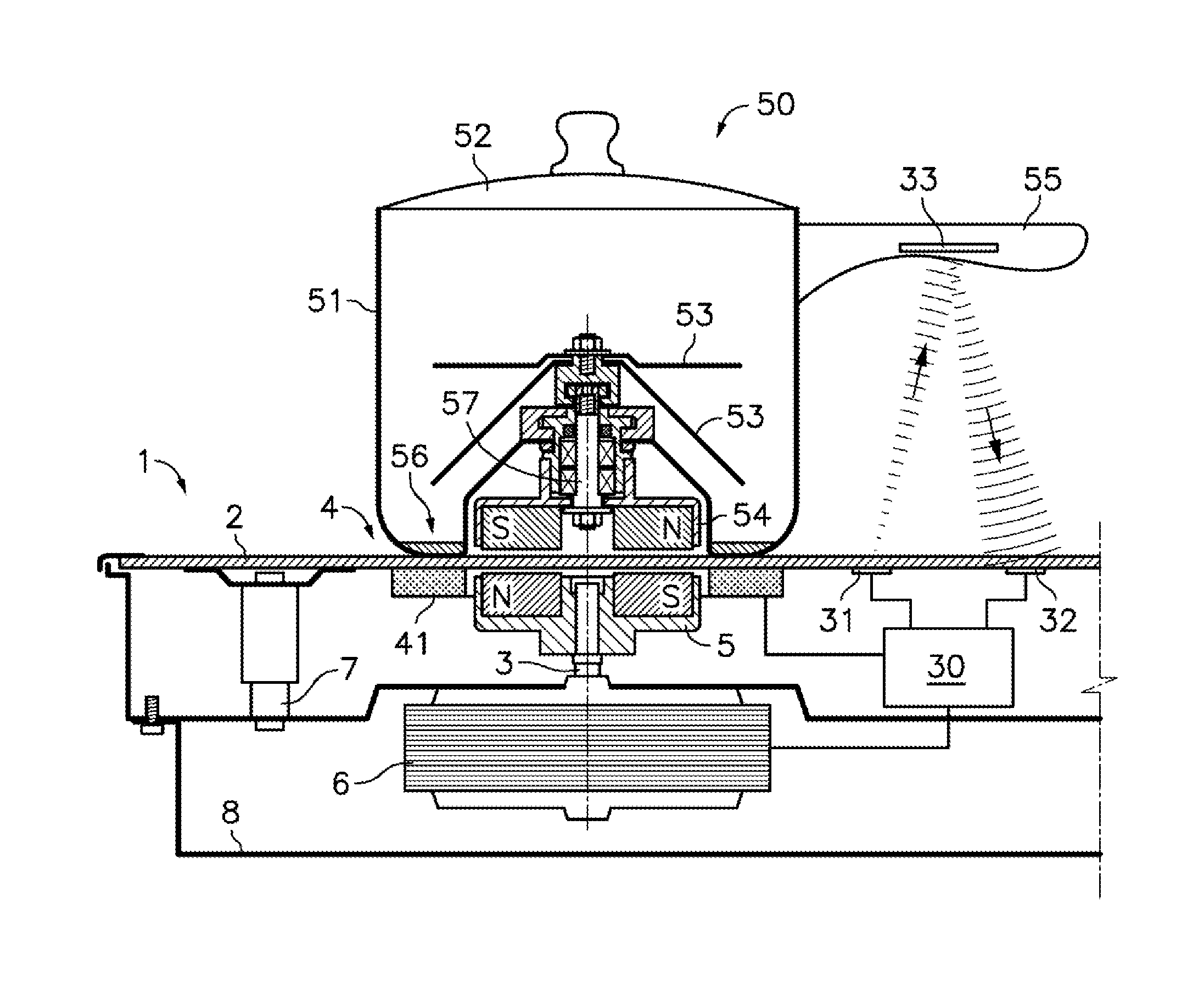
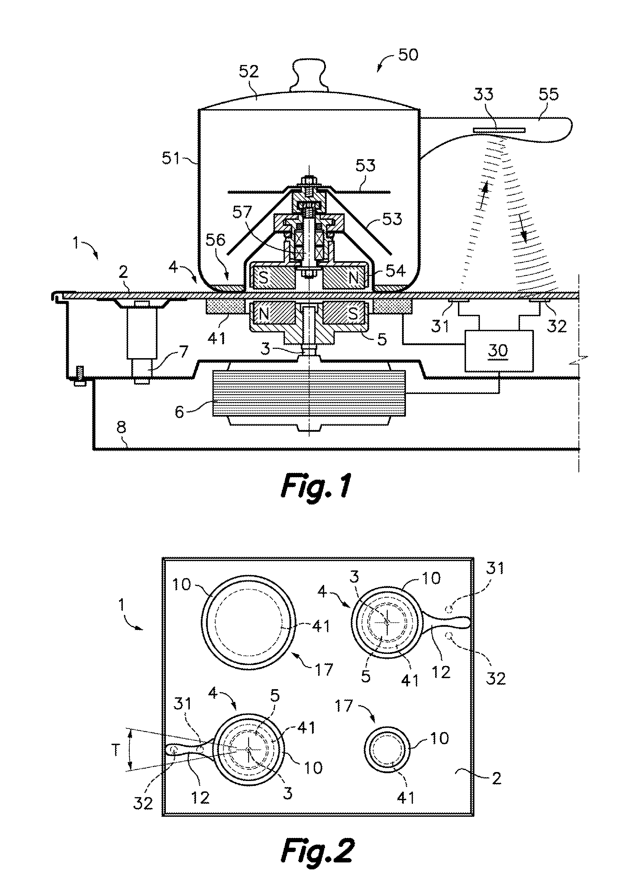
[0042]Referring first to FIG. 1, there is shown a cooking system according to the present invention which includes a cooking hob 1 and a cooking vessel 50.

[0043]The mentioned cooking hob 1 comprises a continuous glass or glass ceramic support plate 2 which has a treatment area 4 capable of supporting the mentioned cooking vessel 50, and a lower magnetic coupling member 5 connected to a drive shaft 3 perpendicular to the support plate 1. The drive shaft 3 is rotatably supported at said treatment area 4 below the support plate 2. An electric drive motor 6 is operatively connected for rotating said lower magnetic coupling member 5. In the illustrated embodiment, the electric drive motor 6 is directly connected to the drive shaft 3, although there can alternatively be mechanical transmission between the electric drive motor 6 and the drive shaft 3.

[0044]The treatment area 4 is associated with an electric heating device 41, such as for example an electromagnetic induction heater or an el...

second embodiment

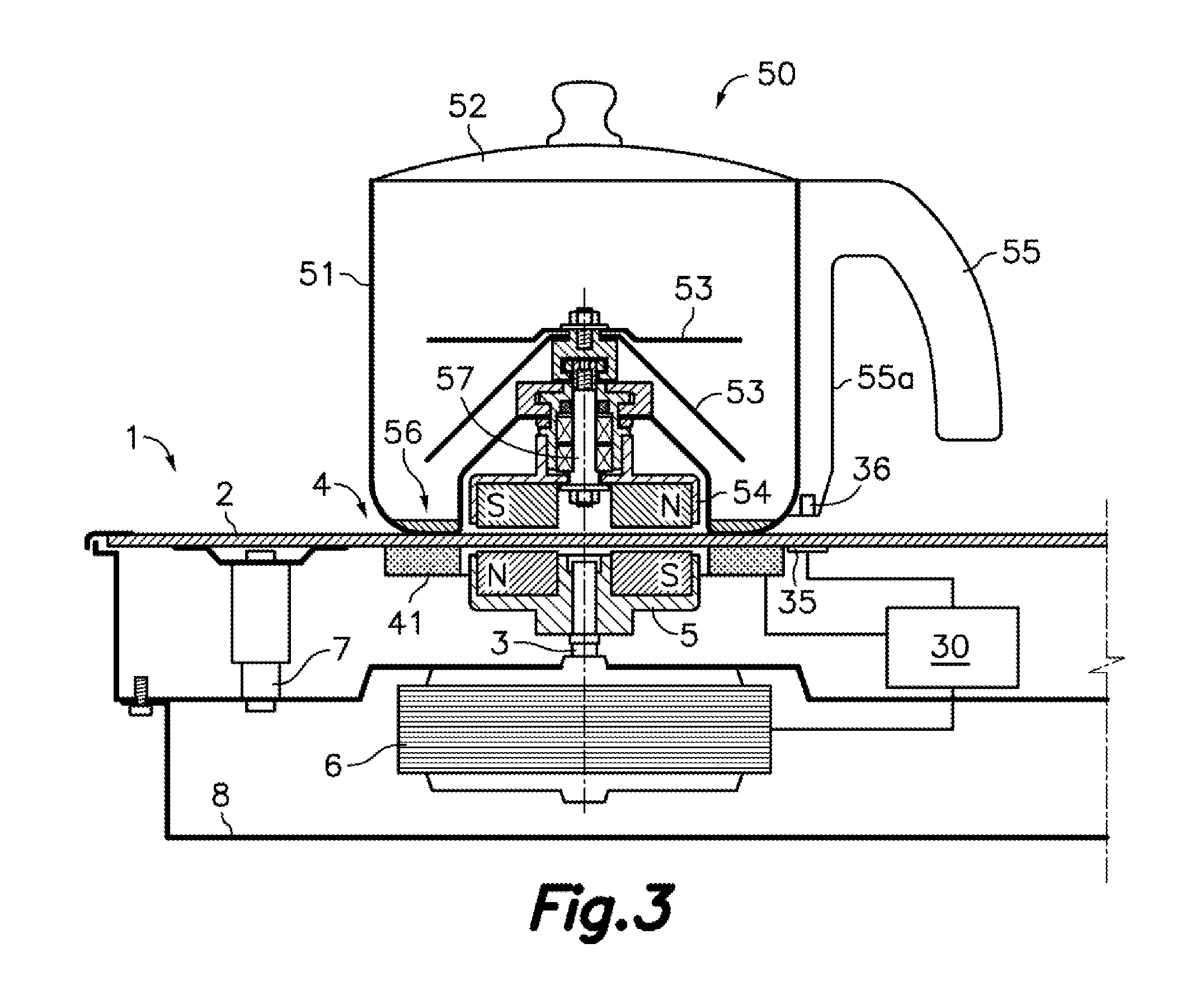
[0056]In the second embodiment shown in FIG. 3, the mentioned appendage 55 includes a fixing portion 55a of a handle extending adjacent to an outer surface of the vessel wall 51 from the handle until close to the bottom 56 thereof, although it could alternatively be any other appendage fixed or formed in the vessel wall 51. The permanent magnet 36 is located at a lower end of said fixing portion 55a of the appendage 55, such that when the cooking vessel is placed on the support plate 2, the permanent magnet 36 is close enough to the support plate 2 to be detected by the Hall effect sensor 35 arranged below it.

[0057]The Hall effect sensor 35 is arranged in a position suitable for detecting a magnetic field generated by the permanent magnet 36 housed in the appendage 55 of the cooking vessel 50 when the cooking vessel 50 is on the treatment area 4 with the appendage 55 at the predetermined angular position indicated in the support plate 2 by means of a second visual indication 12 simi...

third embodiment

[0062]In the third embodiment shown in FIG. 4, an energy storage device 39 connected for supplying electric current to the wave emitter 34 is housed inside the appendage 55 of the cooking vessel 50. The mentioned energy storage device 39 can comprise, for example, one or more disposable batteries or preferably one or more rechargeable batteries.

[0063]FIG. 5 shows a variant of the third embodiment, where the cooking vessel 50 comprises, for example in an upper region of the appendage 55, a photovoltaic cell 40 exposed to ambient light L and connected for charging an energy storage device 39, such as, for example a rechargeable battery or an ultracapacitor, which in turn is configured and arranged for supplying electric current to said wave emitter 34.

[0064]FIG. 6 shows another variant of the third embodiment, where the cooking hob 1 comprises an energy emitting device 37 and the cooking vessel 50 comprises an energy receiving device 38 configured and arranged for receiving energy wir...


PUM


Abstract

The cooking hob (1) comprises a continuous glass or glass ceramic support plate (2) having a treatment area (4) capable of supporting a cooking vessel (50). A drive motor (6) is operatively connected for rotating a lower magnetic coupling member (5) located below the support plate (2) at the treatment area (4). The cooking vessel (50) is provided with rotary blades (53) connected to an upper magnetic coupling member (54) magnetically coupleable to the lower magnetic coupling member (5) through the support plate (2). The cooking hob (1) and the cooking vessel (50) comprise respective components of detection means for detecting an angular position change of the cooking vessel (50) in relation to the treatment area (4) and electronic control means (30) are configured for modifying or stopping the operation of the electric drive motor (6) when the angular position change is detected.

Description

FIELD OF THE ART[0001]The present invention relates to a cooking system including a cooking hob and a cooking vessel, wherein the cooking hob is provided with a continuous glass or glass ceramic support plate and driving means located below the support plate for driving rotary blades installed inside the cooking vessel when the cooking vessel is supported on the support plate, and wherein the driving means comprise a magnetic coupling device acting through the support plate.BACKGROUND OF THE INVENTION[0002]Patent U.S. Pat. No. 5,549,382 describes a cooking hob provided with a support plate having several cooking areas, in each of which a cooking vessel can be supported. The hob includes heating means associated with each cooking area and driving means aligned with one of the cooking areas. The driving means comprise a lower magnetic coupling member driven by a motor for rotating below the support plate in a position close enough to it to magnetically transmit torque to an upper magn...

Claims


Application Information

Patent Timeline
Patent Type & Authority Applications(United States)
IPC IPC(8): A47J36/16A47J27/62A47J43/046H05B3/68H05B3/74
CPCA47J36/165H05B3/685A47J27/62A47J43/0465H05B3/746H05B6/1209H05B2213/06A47J36/321
Inventor ALET VIDAL, JOSEPTRENCH ROCA, LLUIS
Owner ELECTRODOMESTICOS TAURUS
Why Eureka
Try Eureka