IBD Expandable Ti

a technology of ibd and ti, which is applied in the field of expanding interbody spacers, can solve the problems of destabilizing the spine, affecting the quality of life of patients, and affecting the quality of life of patients, and achieves the effect of reducing the trauma of ali

Inactive Publication Date: 2016-03-17
NEXUS SPINE L L C
View PDF20 Cites 14 Cited by
  • Summary
  • Abstract
  • Description
  • Claims
  • Application Information

AI Technical Summary

Benefits of technology

[0014]Implementation of the invention provides an expandable interbody spacer capable of being used in minimally invasive spinal fusion procedures such as PLIF and TLIF while providing a final implant size more commonly in use with more-invasive spinal fusion procedures such as ALIF, XLIF, and DLIF. Additionally implementation of the invention can also be used to minimize the trauma of ALIF, XLIF, or DLIF surgical approaches by minimizing the needed surgical window. Implementation of the invention also provides methods for manufacturing such interbody spacers and methods for using such interbody spacers.

Problems solved by technology

Additionally, the anterior longitudinal ligament must be cut as part of the surgery, which may further destabilize the spine.
The necessary techniques may result in higher levels of blood loss as well as other unwanted side effects such as retrograde ejaculation.
Furthermore, a second surgeon (e.g., a vascular surgeon) is often required, with accompanying increased costs.
Because the implant is larger, there are increased costs of manufacture for the device.
The lateral approaches, however, are limited by issues of access, with access to the L4-L5 interbody space being difficult and access to the L5-S1 space being impossible.
One of the difficulties with such surgery is the potential for damage to nerves disturbed during surgery, with significant numbers of patients reporting leg pain six to twelve months after surgery.
Additionally, subsidence issues remain, and where additional stability is to be achieved through placement of posterior screws, etc., the patient also must be repositioned for posterior access.
However, using conventional techniques and implants, the posterior approach involves challenges of mobilization of the spinal cord, a small graft window, and conventionally only small interbody spacers such as from 10-11 mm can be placed through the small graft window.
The small interbody spacer size generally means that the interbody spacer cannot serve as a standalone implant: additional support through posterior pedicle screws, rods, and / or plates is generally required.
Furthermore, the placement and implant size restrictions inherent in the posterior approach generally results in the interbody spacer being placed at locations of less dense bone.
Other involved risks include failure to achieve proper lordosis (e.g., due to being placed at a location of lower bone density) and risks associated with any necessary laminectomy associated with the procedure.
However, using conventional techniques and implants, the TLIF approach involves challenges of mobilization of the spinal cord, a small graft window, and conventionally only small interbody spacers such as from 10-11 mm can be placed through the small graft window.
The small interbody spacer size generally means that the interbody spacer cannot serve as a standalone implant: additional support through posterior pedicle screws, rods, and / or plates is generally required.
Furthermore, placement and implant size restrictions inherent in the posterior approach generally results in the interbody spacer being placed at locations of less dense bone.
Other involved risks include failure to achieve proper lordosis (e.g., due to being placed at a location of lower bone density) and risks associated with any necessary laminectomy associated with the procedure.
No current device has allowed for a maximal implant size to be implanted with minimal surgical access.
The complexity of those devices often results in increased manufacturing costs, increased likelihood of failure, and complicated surgical techniques.
The complexity of those devices has resulted in increased manufacturing costs, increased likelihood of failure, and complicated surgical techniques without a significant increase in implanted footprint.
For these and other reasons, there remain unaddressed needs in the area of implanted interbody spacers for use in spinal fusion procedures.

Method used


Image

  • IBD Expandable Ti
  • IBD Expandable Ti
  • IBD Expandable Ti

Examples


Embodiment Construction

[0046]A description of embodiments of the present invention will now be given with reference to the Figures. It is expected that the present invention may take many other forms and shapes, hence the following disclosure is intended to be illustrative and not limiting, and the scope of the invention should be determined by reference to the appended claims.

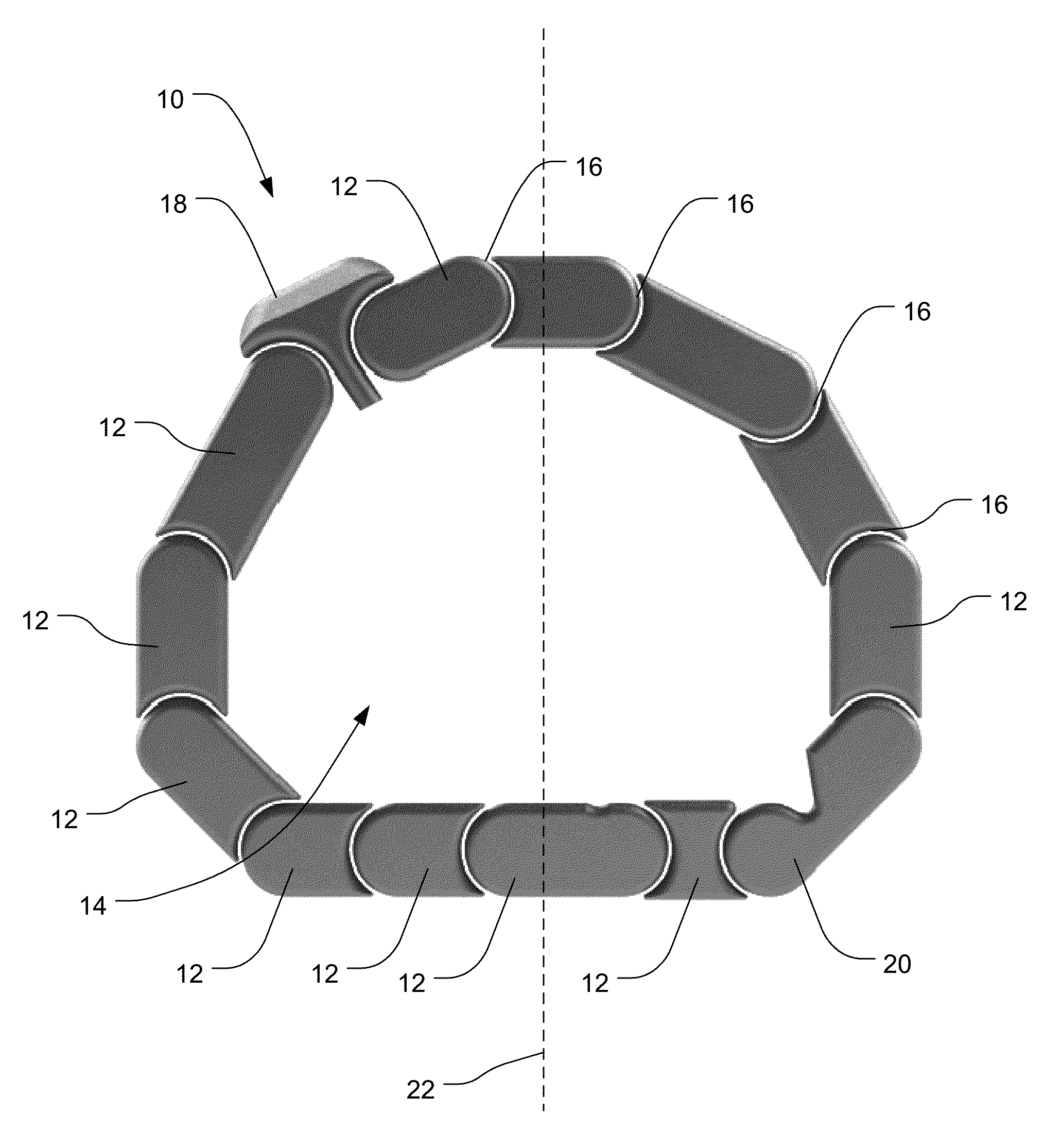
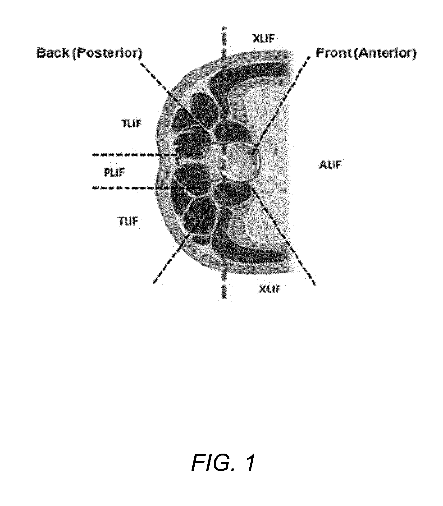
[0047]Embodiments of the invention provide an expandable interbody spacer capable of being used in minimally invasive spinal fusion procedures such as PLIF and TLIF while providing a final implant size more commonly in use with more-invasive spinal fusion procedures such as ALIF, XLIF, and DLIF. Additionally embodiments of the implant can also be used to minimize the trauma of ALIF, XLIF, or DLIF surgical approaches by minimizing the needed surgical window. Embodiments of the invention also provide methods for manufacturing such interbody spacers and methods for using such interbody spacers.

[0048]According to embodiments of the inve...


PUM


Abstract

An expandable interbody spacer for use in spinal fusion procedures includes a plurality of rigid segments connected by flexible connections to form a ring encompassing and defining a hollow central area of variable dimensions. The flexible connections between the plurality of rigid segments may include flexible regions formed between the rigid segments or a continuous flexible member extending along a multisegmented region. The flexible regions formed between the rigid segments may be integrally formed with the rigid segments. One or more of the flexible regions formed between the rigid segments may include a plurality of flexure divisions extending between adjacent rigid segments. One or more of the flexible regions formed between the rigid segments may include a flexure extending between adjacent rigid segments. The rigid segments may include surfaces to limit the range of motion between adjoining rigid segments.

Description

CROSS-REFERENCE TO RELATED APPLICATIONS[0001]This application claims the benefit of U.S. Provisional Application No. 62 / 050,038, filed Sep. 12, 2014.BACKGROUND OF THE INVENTION[0002]1. Field of the Invention[0003]The present invention relates to spinal fusion, and more particularly to an expanding interbody spacer for use in spinal fusion procedures.[0004]2. Background and Related Art[0005]Spinal fusion is a surgical procedure used to correct problems with the vertebrae in the spine. Spinal fusion is used to fuse or rigidly join two or more adjacent vertebrae so that they heal into a single solid bone. One general type of spinal fusion involves removing the intervertebral disc. When the disc space has been cleared out, a metal, plastic, or bone spacer is implanted between the adjoining vertebrae in the space previously occupied by the intervertebral disc. The spacers or cages often contain bone graft material to promote bone healing and to facilitate fusion. Once the spacer or cage ...

Claims


Application Information

Patent Timeline
Patent Type & Authority Applications(United States)
IPC IPC(8): A61F2/44
CPCA61F2/4455A61F2002/4415A61F2002/448A61F2002/2817A61F2002/30772A61F2002/30784A61F2002/3093A61F2002/4687A61F2002/30462A61F2002/30471A61F2002/30545A61F2002/3055A61F2002/30571A61F2002/30733A61F2002/30593
Inventor HALVERSON, PETERHAWKES, DAVID
Owner NEXUS SPINE L L C
Why Eureka
Try Eureka