Vaporized fuel processing apparatus

a fuel processing and vaporization technology, applied in the direction of electric control, charge feed system, non-fuel substance addition to fuel, etc., can solve the problems of inefficient heating of purge air by the heater, reducing the space efficiency of the fin heat exchanger, and reducing the efficiency of the heat exchanger heating. the effect of fuel vapor desorption efficiency

Inactive Publication Date: 2016-03-17
AISAN IND CO LTD
View PDF3 Cites 6 Cited by
  • Summary
  • Abstract
  • Description
  • Claims
  • Application Information

AI Technical Summary

Benefits of technology

[0017]According to this aspect of the disclosure, it is able to uniformly supply the purge air to the entire heater depe

Problems solved by technology

However, the adsorbent has an adsorption capacity for the fuel vapor and cannot adsorb the fuel vapor over this adsorption capacity.
However, when desorbing the fuel vapor from the adsorbent, the temperature of the adsorbent tends to decrease due to heat of vaporization of the fuel vapor.
In the case of the vaporized fuel processing apparatus disclosed in Japanese Laid-Open Patent Publication No. 2012-102722, because the heating element is positioned at the center of the fin heat exchangers with respect to the flowing direction

Method used


Image

  • Vaporized fuel processing apparatus
  • Vaporized fuel processing apparatus
  • Vaporized fuel processing apparatus

Examples


Embodiment Construction

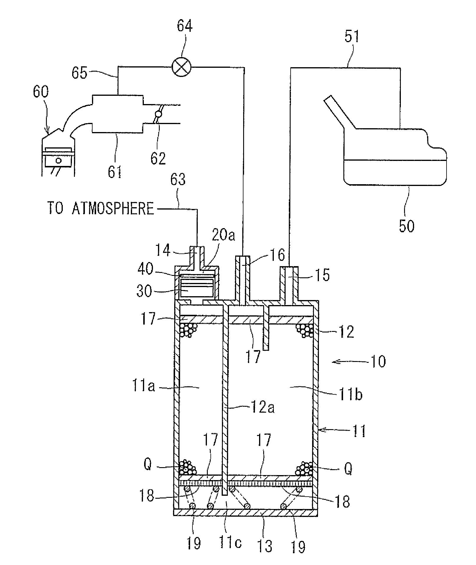
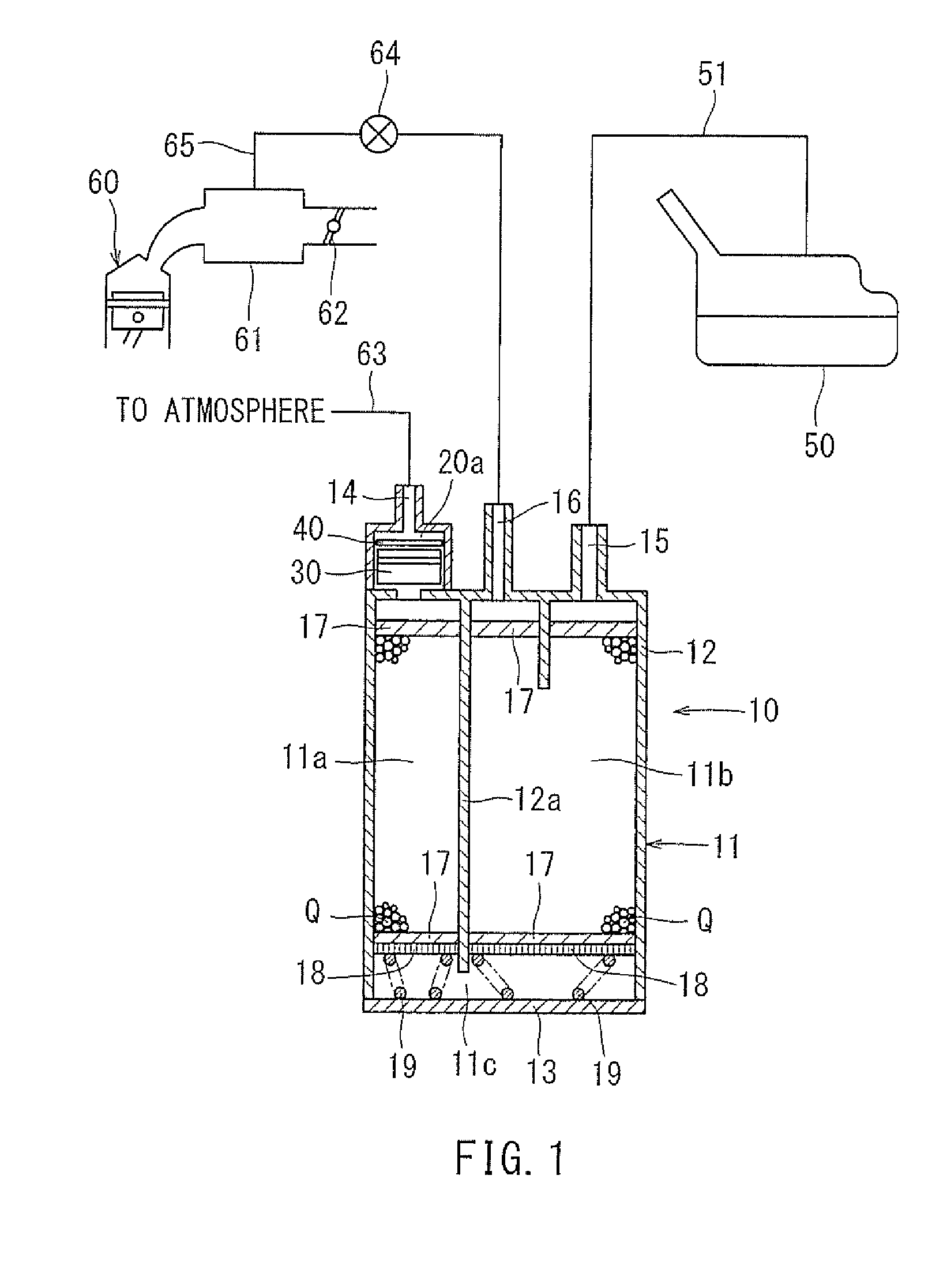
[0030]Each of the additional features and teachings disclosed above and below may be utilized separately or in conjunction with other features and teachings to provide improved vaporized fuel processing apparatuses. Representative examples, which utilize many of these additional features and teachings both separately and in conjunction with one another, will now be described in detail with reference to the attached drawings. This detailed description is merely intended to teach a person of skilled in the art further details for practicing preferred aspects of the present teachings and is not intended to limit the scope of the invention. Only the claims define the scope of the claimed invention. Therefore, combinations of features and steps disclosed in the following detailed description may not be necessary in the broadest sense, and are instead taught merely to particularly describe representative examples. Moreover, various features of the representative examples and the dependent...


PUM


Abstract

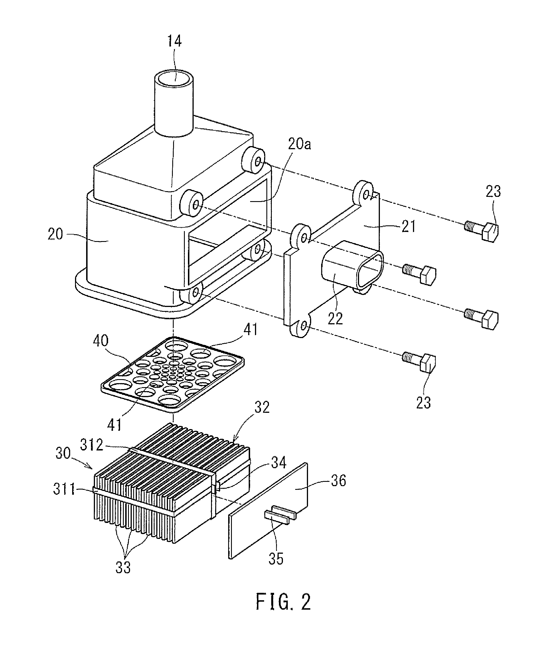
A vaporized fuel processing apparatus has a casing defining an adsorption chamber therein and having a tank port, a purge port, and an atmospheric port. The tank port is connected to a fuel tank. The purge port is connected to an internal combustion engine. The atmospheric port is open to the atmosphere. A heater is disposed between the adsorption chamber and the atmospheric port and has a fin heat exchanger and a heating element. The heating element is configured to generate heat by electricity supply. The fin heat exchanger is joined to the heating element. The surface area of the fin heat exchanger between the heating element and the adsorption chamber is larger than the surface area of the fin heat exchanger between the heating element and the atmospheric port.

Description

CROSS-REFERENCE TO RELATED APPLICATIONS[0001]This application claims priority to Japanese patent application serial number 2014-187347, filed Sep. 16, 2014, the contents of which are incorporated herein by reference in their entirety for all purposes.STATEMENT REGARDING FEDERALLY SPONSORED RESEARCH OR DEVELOPMENT[0002]Not applicable.BACKGROUND[0003]This disclosure relates to a vaporized fuel processing apparatuses having an adsorption chamber, a tank port, a purge port, an atmospheric port and a heater. The adsorption chamber is filled with an adsorbent capable of adsorbing and desorbing fuel vapor vaporized in a fuel tank. The tank port is communicated with the tank port. The purge port is configured to discharge the fuel vapor, which has been desorbed from the adsorbent, to the outside of the adsorption chamber. The atmospheric port is open to the atmosphere. The heater is disposed between the adsorption chamber and the atmospheric port.[0004]The vaporized fuel processing apparatu...

Claims


Application Information

Patent Timeline
IPC IPC(8): F02M25/08
CPCF02M25/089F02M2025/0881F02M25/0854F02D41/003F02M25/08
Inventor MAKINO, KATSUHIKOKIMOTO, JUNYA
Owner AISAN IND CO LTD
Why Eureka
Try Eureka