Component mounting work support system and component mounting method

a work support system and component technology, applied in the field of component mounting work support system, can solve the problems of dislocation of marking position due to plastic deformation upon forming, difficulty in performing marking work itself, and high cost of marking work, so as to simplify the marking work and improve the work efficiency of component mounting.

Inactive Publication Date: 2016-03-17
KAWASAKI HEAVY IND LTD
View PDF242 Cites 22 Cited by
  • Summary
  • Abstract
  • Description
  • Claims
  • Application Information

AI Technical Summary

Benefits of technology

[0021]By the component mounting work support system and the component mounting method using the system according to the present invention, the conventional marking work becomes unnecessary or the marking work is simplified by using the mixed reality technology, and therefore work efficiency of component mounting can be considerably improved.

Problems solved by technology

However, marking work itself is sometimes difficult to perform when the dimension of a workpiece on which a component is mounted is large or when a workpiece has a curved surface, and therefor there is a case that a lot of time is consumed for the marking work.
Also, there is also a problem that, when marking is performed before forming a workpiece, a marking position is dislocated due to plastic deformation upon forming.
As a result, there is a case that the regression work occurs and work efficiency declines.
Also, in an inspection after a workpiece is mounted, there is a problem that the quality of mounting state cannot be judged intuitively since it is necessary to confirm the mounting state with respect to drawings or the like.

Method used


Image

  • Component mounting work support system and component mounting method
  • Component mounting work support system and component mounting method
  • Component mounting work support system and component mounting method

Examples


Embodiment Construction

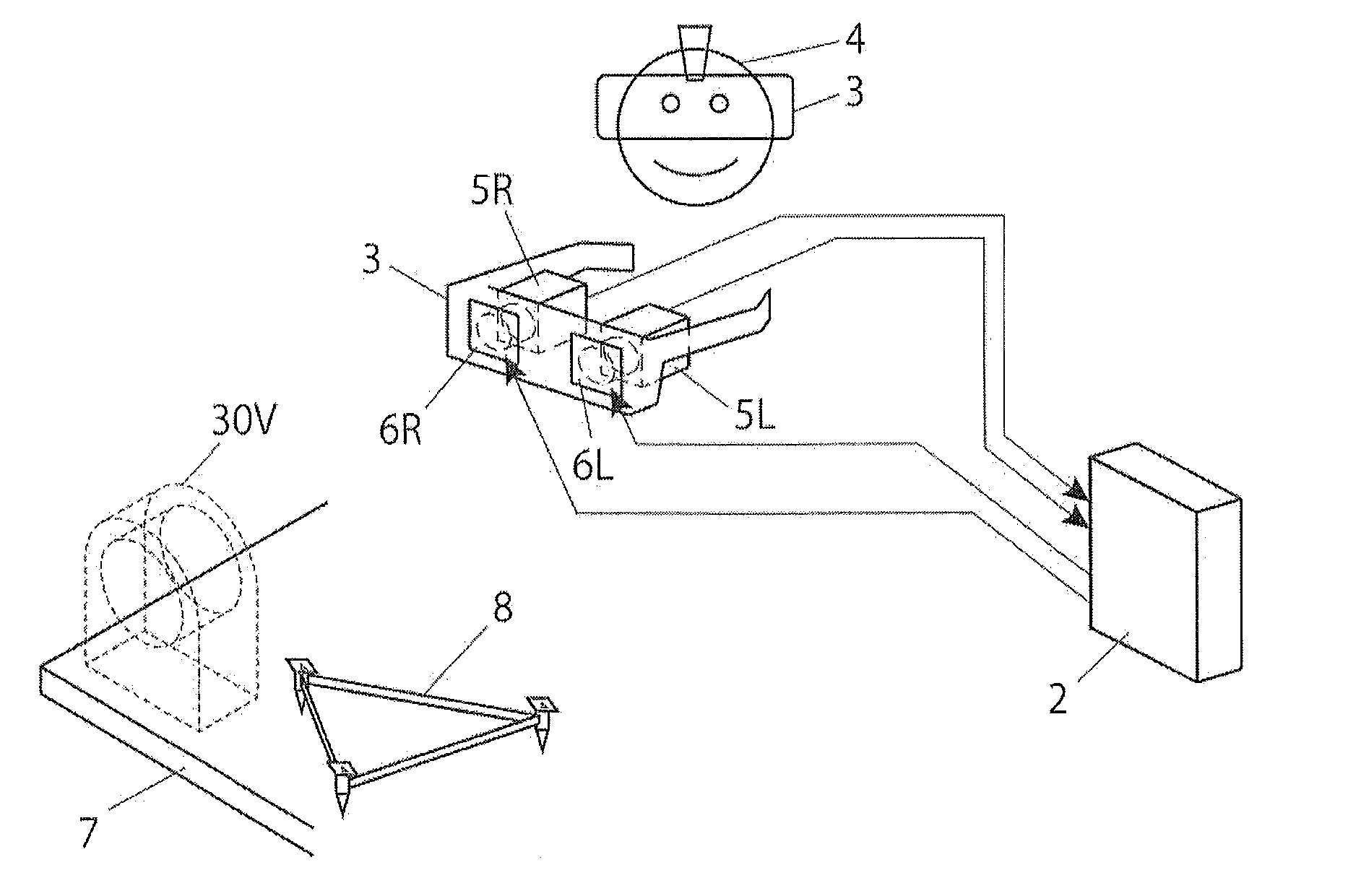
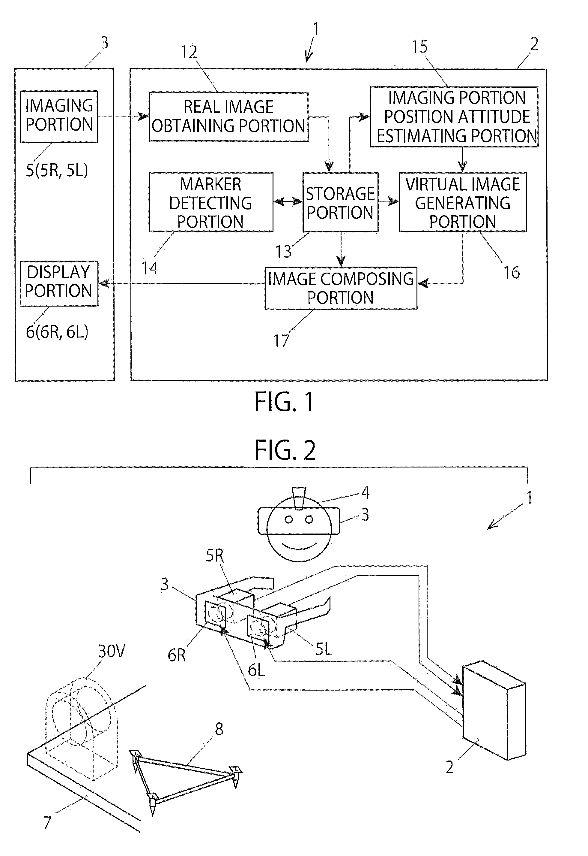
[0029]Hereunder, a component mounting work support system according to an embodiment of the present invention will be described. Note that, although the component mounting work to be supported by the system is typically a component tack welding work to a workpiece, various component mounting works to a workpiece other than the component tack welding work can also be supported.

[0030]As the component mounting work support system according to the embodiment uses the mixed reality technology, first, the mixed reality technology will be briefly explained.

[0031]As previously mentioned, the mixed reality technology is a video technology which superimposes an image of a virtual space on an image of a real space at an arbitrary viewpoint and presents a composite image obtained in this manner to an observer so as to integrate the real world with the virtual world seamlessly in real time.

[0032]Namely, the mixed reality technology provides an observer with a composite image obtained by composin...


PUM


Abstract

The system has an imaging unit configured to image a work space at a viewpoint position in a visual line direction of a worker together with a workpiece on which a component is mounted, a position attitude information obtaining unit configured to obtain a position attitude information which indicates a relative position attitude relation between the viewpoint of the worker and the workpiece in the work space, a virtual image generating unit configured to generate a three-dimensional virtual image indicating the component after being mounted at the viewpoint position in the visual line direction, an image composing unit configured to generate a composite image by superimposing the virtual image on a real image of the work space, and a display unit configured to display the composite image. According to the system, efficiency of the component mounting work can be considerably improved by using the mixed reality technology.

Description

TECHNICAL FIELD[0001]The present invention relates to a component mounting work support system for supporting mounting work of a component using a mixed reality technology, particularly relates to a component mounting work support system suitable for supporting component tack welding work and a component mounting method using the system.BACKGROUND ART[0002]Conventionally, when a component such as a hanging metal fitting is welded to a workpiece, a marking 42 is previously performed to a position of a workpiece 41 on which a component 41 is mounted as illustrated in FIG. 7(a), and a worker performs tack welding of the component 41 with the marking 42 as a mark (FIG. 7(b)).[0003]However, marking work itself is sometimes difficult to perform when the dimension of a workpiece on which a component is mounted is large or when a workpiece has a curved surface, and therefor there is a case that a lot of time is consumed for the marking work.[0004]Also, there is also a problem that, when mar...

Claims


Application Information

Patent Timeline
Patent Type & Authority Applications(United States)
IPC IPC(8): G02B27/01G06T19/00G06T7/00H04N13/04
CPCG06T19/006G06T7/001G06T7/0044H04N13/044G02B27/0172G02B2027/014G06T2207/20221G02B2027/0178G02B2027/0134G02B2027/0138G06T2200/04G06Q10/06G09B19/003G02B27/017G02B2027/0187G02B2027/0141H04N13/156H04N13/344
Inventor SHIKODA, SHIGEKAZUNAKAMURA, NAOHIRONAKANO, SHINICHIAKAMATSU, MASAHIKOYONEMOTO, SHINGOTOKAI, DAISUKEKOUMOTO, TAKASHI
Owner KAWASAKI HEAVY IND LTD
Why Eureka
Try Eureka