Method and apparatus for producing molded article of fiber-reinforced plastic

a fiber reinforced plastic and molded article technology, applied in woodworking apparatus, domestic applications, food shaping, etc., can solve the problems of unavoidable formation of unavoidable unavoidable area, liquid resin cannot be readily transferred from the depression toward the protruding portion, and liquid resin cannot be readily transferred to the downstream side of the narrow portion without application of a sufficient pressure, so as to reduce the inspiratory force in the subsequent molding process, reduce the effect of force and high yield

Inactive Publication Date: 2016-03-24
HONDA MOTOR CO LTD
View PDF4 Cites 13 Cited by
  • Summary
  • Abstract
  • Description
  • Claims
  • Application Information

AI Technical Summary

Benefits of technology

[0035]In the case that the liquid resin is supplied excessively above the base fiber material, the liquid resin is blocked by the second sealing member. Therefore, the liquid resin can be prevented from leaking outside of the production cavity. Thus, lack of liquid resin caused by leakage of the liquid resin can be prevented, and the occurrence of an unimpregnated area in the molded FRP article can be prevented. Consequently, a molded FRP article of satisfactory strength can be produced with high yield.
[0036]Furthermore, since the liquid resin is blocked by the second sealing member, the liquid resin can be prevented from being drawn into the sealed room and the exhaust passage that communicates with the sealed room. Thus, a reduction in the inspiratory force in a subsequent molding process can be prevented.
[0037]In addition, even if a valve is formed in the exhaust passage, it is not necessary to take apart and clean the valve or to replace the valve. For these reasons, a greater number of moldings can be performed per unit time, so that molded FRP articles can be produced with improved efficiency.
[0038]Thus, in the present invention, the resin can be spread satisfactorily up to the edge of the base fiber material, and molded FRP articles having a complicated three-dimensional shape, a large thickness, or a high fiber volume content can be produced efficiently with satisfactory strength and high yield.
[0039]After the first predetermined amount of the liquid resin has been supplied, and until the second predetermined amount of the liquid resin starts to be supplied to the production cavity, the upper mold may be moved relatively toward the lower mold in a continuous manner. In other words, the third and fourth steps may be carried out successively while the upper mold is moved relatively toward the lower mold.
[0040]After the first predetermined amount of the liquid resin has been supplied and until the second predetermined amount of the liquid resin starts to be supplied, supply of the liquid resin may be stopped. Alternatively, a smaller amount of the liquid resin may be supplied continuously to the production cavity. The smaller amount is smaller than the first and second predetermined amounts.

Problems solved by technology

However, for example, in the case that a depression and a protrusion have a large height difference in the cavity, the liquid resin cannot be readily transferred from the depression toward the protrusion.
Furthermore, in the case that a portion having a significantly small cross-sectional area (a narrow portion) is formed in a flow path of the liquid resin, the liquid resin cannot readily be transferred to the downstream side of the narrow portion without application of a sufficient pressure.
Thus, in the known techniques, an unimpregnated area is unavoidably formed in some cases.
Thus, the liquid resin is not sufficiently transferred through such a narrow portion, and an unimpregnated area is unavoidably formed in some cases.

Method used


Image

  • Method and apparatus for producing molded article of fiber-reinforced plastic
  • Method and apparatus for producing molded article of fiber-reinforced plastic
  • Method and apparatus for producing molded article of fiber-reinforced plastic

Examples


Embodiment Construction

[0061]A preferred embodiment of the molding method of the present invention for producing a molded article of a fiber-reinforced plastic (a molded FRP article) using the molding apparatus of the present invention will be described in detail below with reference to the accompanying drawings.

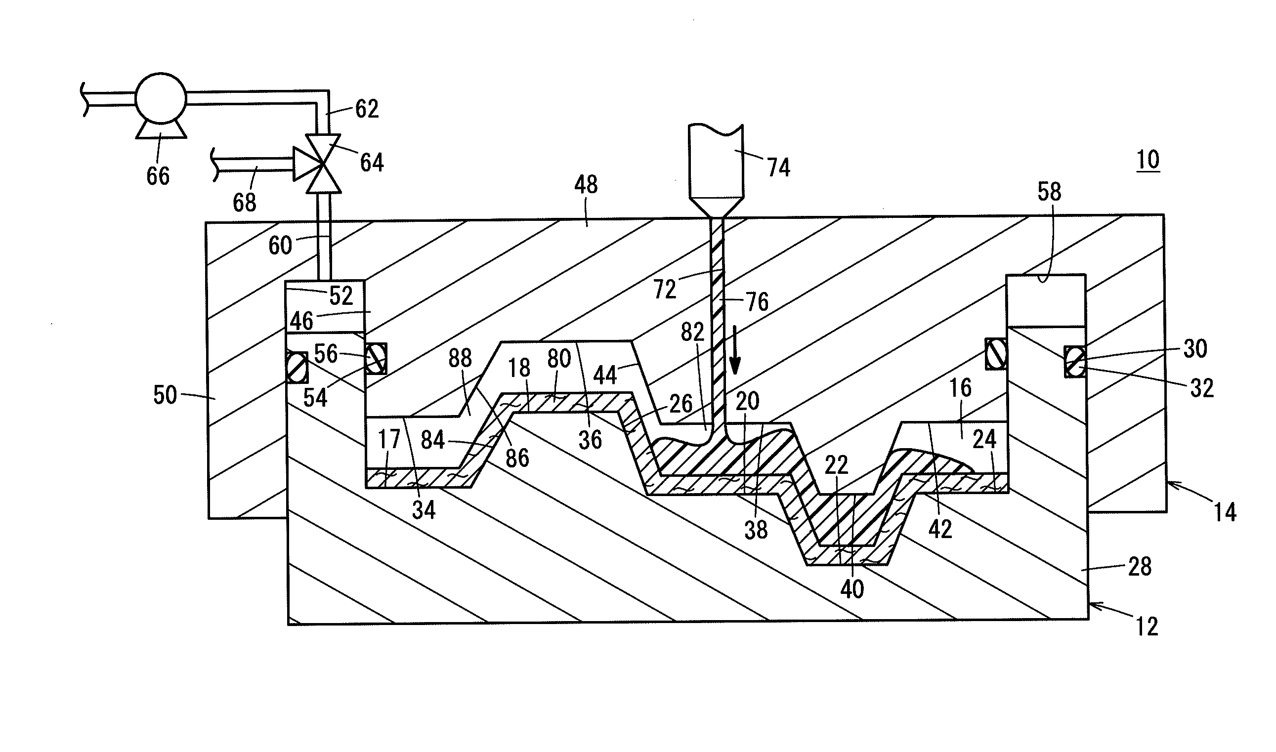
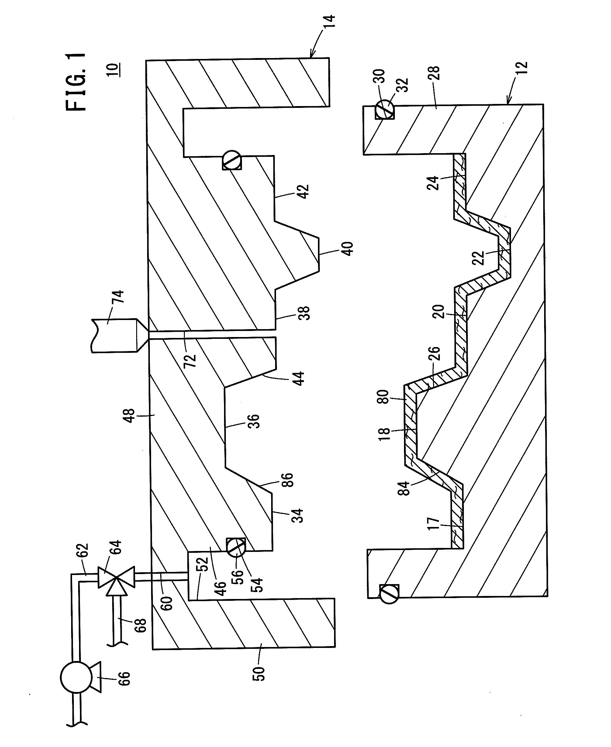
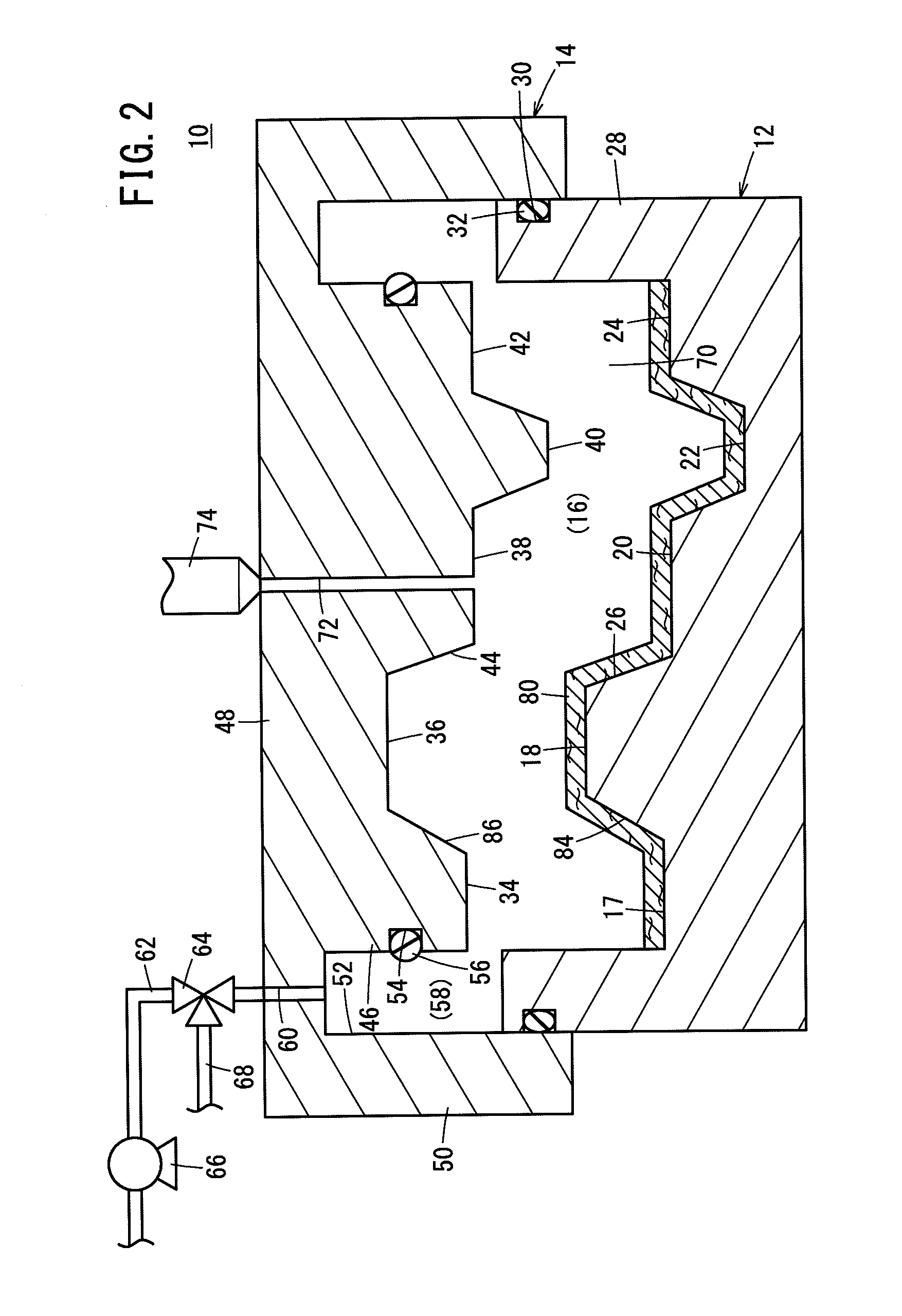
[0062]FIG. 1 is a schematic vertical cross-sectional view of a principal part of a fiber-reinforced plastic molding apparatus 10 (hereinafter referred to simply as a molding apparatus 10) according to the present embodiment. The molding apparatus 10 contains a lower mold 12 and an upper mold 14 as a molding tool. A production cavity 16 is formed between the lower mold 12 and the upper mold 14 (see FIGS. 3 to 6). In FIG. 1, the molding apparatus 10 is shown in an open state.

[0063]The lower mold 12 is a stationary mold, which is fixed in a given position. A first flat wall 17, a first protrusion 18, a second flat wall 20, a first depression 22, and a third flat wall 24 are arranged on a cavity formi...


PUM

PropertyMeasurementUnit
thicknessaaaaaaaaaa
pressureaaaaaaaaaa
volume ratioaaaaaaaaaa

Abstract

A lower mold and an upper mold are combined to form an enclosed space containing a production cavity and a sealed room. A base fiber material is placed in the production cavity. The production cavity has a first space and a second space. After a gas in the enclosed space has been discharged, a first predetermined amount of a liquid resin is supplied to the first space. After supply of the liquid resin is stopped (or while the liquid resin is continuously supplied), the upper mold is lowered relatively further toward the lower mold, whereby the volume of the production cavity becomes reduced. Preferably, a second predetermined amount of the liquid resin is supplied to the first space having a large volume, whereupon the supplied liquid resin flows from the first space into the second space having a small volume.

Description

CROSS-REFERENCE TO RELATED APPLICATION[0001]This application is based upon and claims the benefit of priority from Japanese Patent Application No. 2014-189924 filed on Sep. 18, 2014, the contents of which are incorporated herein by reference.BACKGROUND OF THE INVENTION[0002]1. Field of the Invention[0003]The present invention relates to a method and an apparatus for impregnating a base fiber material with a liquid resin to produce a molded article of a fiber-reinforced plastic.[0004]2. Description of the Related Art[0005]Fiber-reinforced plastics, which are composites made of base fibers and resins, have been known as lightweight high-strength materials. Molded articles made from such fiber-reinforced plastics have recently been used in components for car bodies and airplanes.[0006]Molded articles of fiber-reinforced plastics (hereinafter referred to as molded FRP articles) can be produced, for example, by an RTM (Resin Transfer Molding) method. In the RTM method, a base fiber mater...

Claims


Application Information

Patent Timeline
Patent Type & Authority Applications(United States)
IPC IPC(8): B29C45/34B29C45/00
CPCB29C45/34B29L2031/00B29C45/0005B29C70/48B29C33/0038B29C2791/006B29C70/467
Inventor KOBAYASHI, MASATOSHIDAN, KOJI
Owner HONDA MOTOR CO LTD
Why Eureka
Try Eureka