
Driver assistance system for motor vehicles

a technology for motor vehicles and drivers, applied in the direction of process and machine control, instruments, navigation instruments, etc., can solve the problems of inability to uniquely classify passenger cars, two-wheeled vehicles, pedestrians, vehicles that cannot accurately assess relative velocity, etc., to improve safety and ride comfort.

Active Publication Date: 2016-03-24
ROBERT BOSCH GMBH
View PDF7 Cites 31 Cited by
  • Summary
  • Abstract
  • Description
  • Claims
  • Application Information

AI Technical Summary

Benefits of technology

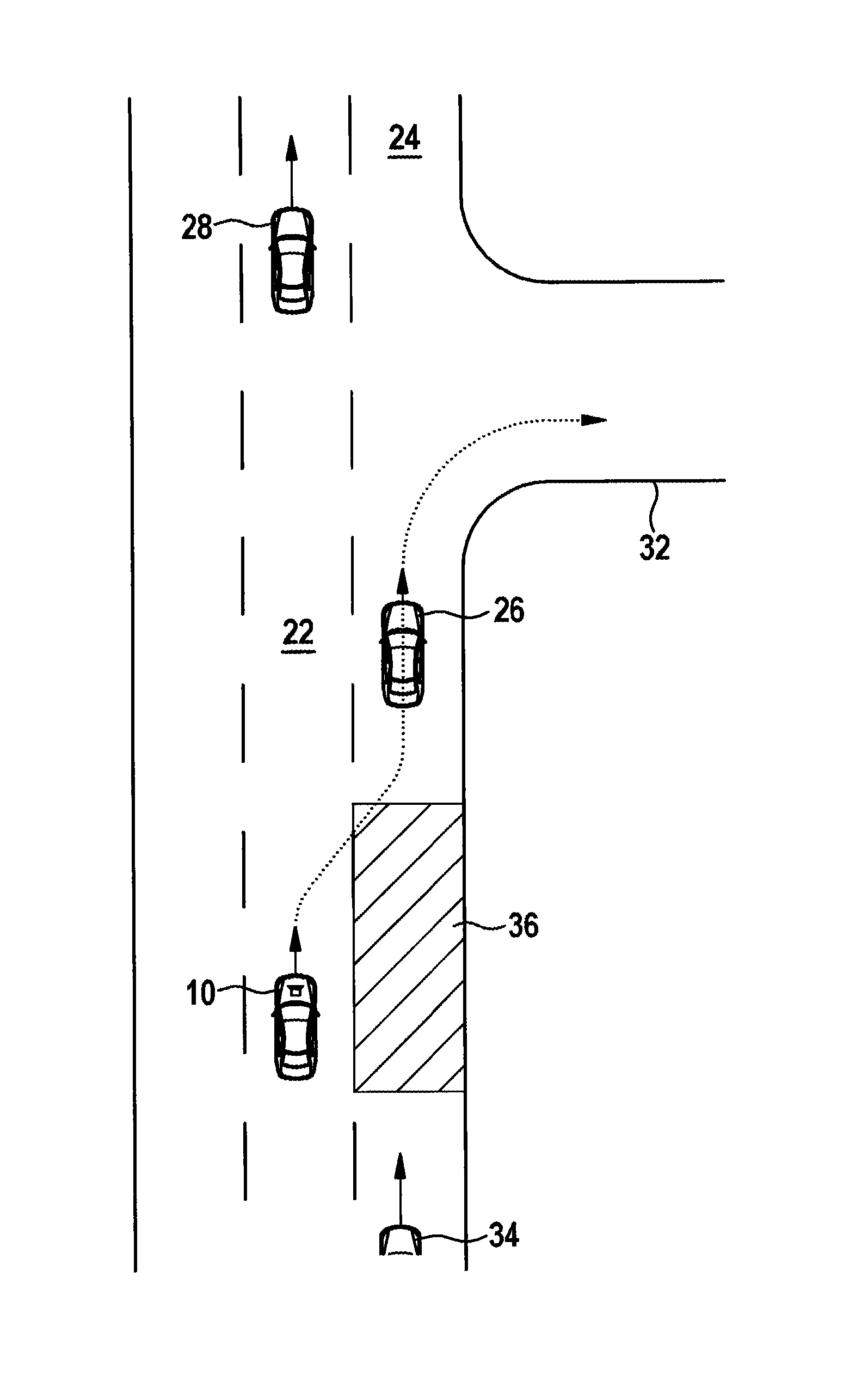
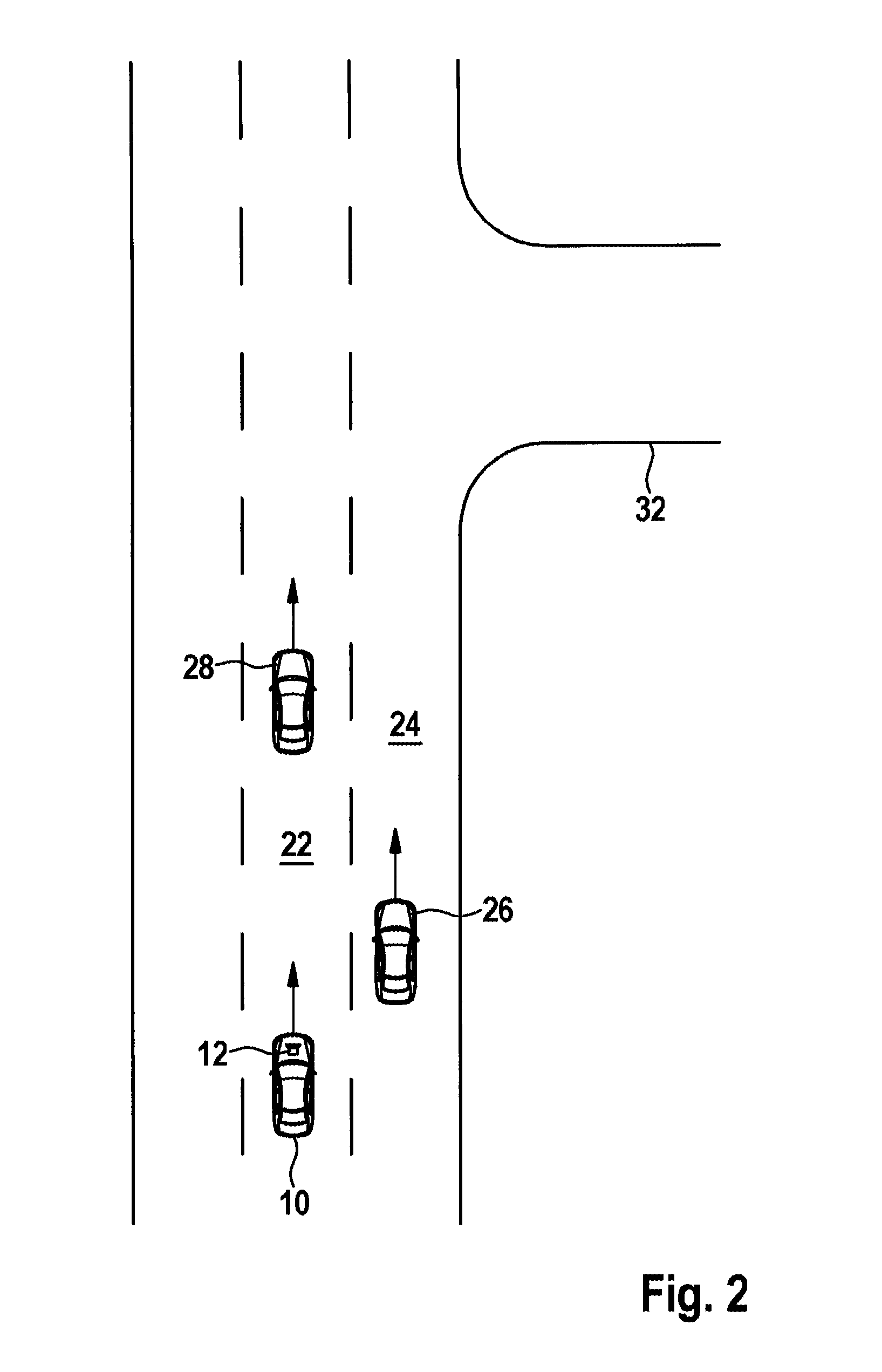
The present invention is a driver assistance system with an additional function that improves safety and comfort during turning processes. The system uses sensor technology to identify gaps or windows in front of and behind a vehicle that allow for safe movement into an adjacent lane. The system then modifies the vehicle's velocity to match the velocity of the adjacent lane, making the turning process as smooth as possible. The necessary sensory components for the system are already present, and the system can be easily integrated into existing electronic data processing systems.

Problems solved by technology

For example, such a camera can make it easier to classify objects that had been recognized by the radar systems, but, on the basis of the radar signals, were not able to be uniquely classified as passenger cars, trucks, two-wheeled vehicles, pedestrians or the like.
A dangerous situation can arise when another vehicle is located in the blind spot in the adjacent lane, or when a vehicle is coming closer at a higher velocity in the adjacent lane, and the driver of the subject vehicle is not able to accurately assess the relative velocity.
It is understood that these boundaries are not static, but move relative to the subject vehicle, so that adapting the velocity of the subject vehicle generally does not suffice.

Method used


Image

  • Driver assistance system for motor vehicles
  • Driver assistance system for motor vehicles
  • Driver assistance system for motor vehicles

Examples


Embodiment Construction

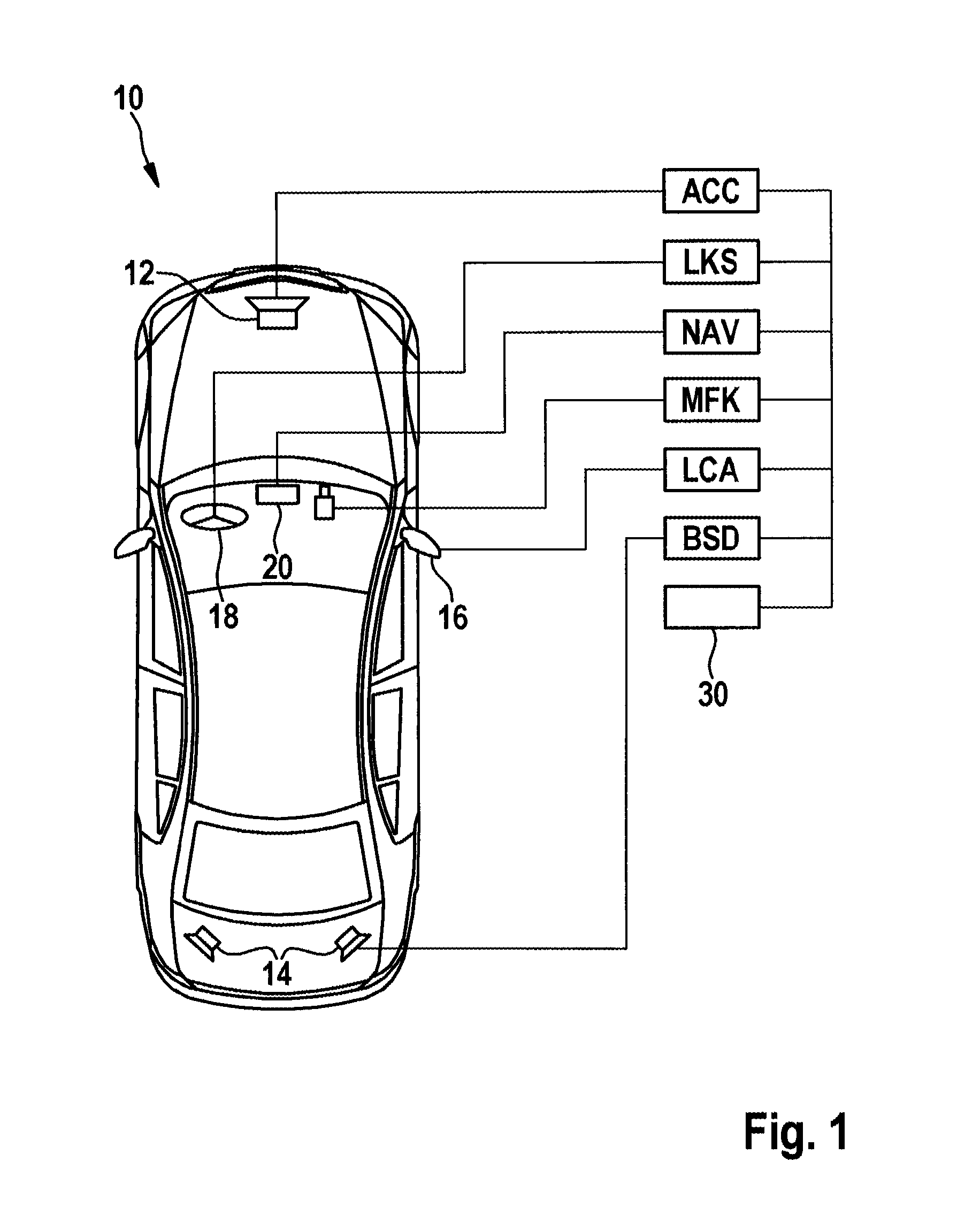
[0023]In a plan view, FIG. 1 schematically shows a motor vehicle 10 that is equipped with a driver assistance system according to the present invention. The driver assistance system is constituted in a generally known manner of an electronic data processing system or of a plurality of mutually cooperating data processing systems that receive input signals from various sensory components and transmit output signals to actuators of the motor vehicle, for example to the drive (engine and transmission management), the brake system and the steering system.

[0024]In the illustrated example, the driver assistance system encompasses a velocity regulation function ACC which, in the first place, evaluates signals from a long-range radar sensor 12 which is installed at the front of the vehicle, locates vehicles in front and other objects in the near field of the subject vehicle 10, and measures the distances and relative velocities thereof. For purposes of the assistance, a multifunction video ...


PUM


Abstract

A driver assistance system for motor vehicles, having a velocity regulation function for regulating the velocity of the subject vehicle to a nominal velocity, and having an adjacent-lane monitoring function, characterized by a turning assistance function which, when the velocity regulation function is active and an incoming signal indicates an imminent turning process that requires crossing an adjacent lane, monitors the traffic in the adjacent lane with the aid of the adjacent-lane monitoring function, and, as a function of locations and velocities of traffic participants in the adjacent lane, determines a spatial and temporal window for moving into the adjacent lane and adapts the nominal velocity to this window.

Description

FIELD OF THE INVENTION[0001]The present invention relates to a driver assistance system for motor vehicles, having a velocity regulation function for regulating the velocity of one's own vehicle to a nominal velocity, and having an adjacent-lane monitoring function.BACKGROUND INFORMATION[0002]Motor vehicles frequently come equipped with electronic driver assistance systems that provide the driver with vehicle guidance support. What are generally referred to as ACC systems (adaptive cruise control) are known, for example, that are used for regulating the velocity of one's own vehicle. During free travel of the vehicle, when there is no vehicle in front in one's own lane, the nominal velocity is a driver-specified velocity. If, on the other hand, a vehicle driving ahead is followed, then the distance thereto is measured using a radar sensor installed in the vehicle, for example, and one's own velocity is adapted to ensure that the vehicle driving ahead is followed at an appropriate co...

Claims


Application Information

Patent Timeline
Patent Type & Authority Applications(United States)
IPC IPC(8): B60W30/18B60W10/20B60W30/12B60W30/16B60W40/04B60W50/14B60W50/16G01C21/34
CPCB60W30/18163B60W30/12B60W30/162G01C21/34B60W10/20B60W50/16B60W50/14B60W40/04G01C21/3407B60W30/14B60W30/18145B60W2540/20B60W2556/50
Inventor FUEHRER, THOMAS
Owner ROBERT BOSCH GMBH
Learn More