Light Source Device and Display Apparatus

Active Publication Date: 2016-03-24
SAKAI DISPLAY PROD
View PDF6 Cites 4 Cited by
  • Summary
  • Abstract
  • Description
  • Claims
  • Application Information

AI Technical Summary

Benefits of technology

[0032]According to the present invention, the light source is disposed on the center side of the light guide plate from the notch part in the direction in which the one side face a

Problems solved by technology

However, as described above, when fixing the position of the light guide plate by using the positioning part, the light propagating inside the light guide plate, for example, is reflected by a side face relating to the notch part or the positioning part, such that unintended residual reflected light is generated around the notch part to be emitted to the display panel through the light guide plate.
Thereby, unevenness in luminance occurs in the display panel.
However, in the light source module of Japanese Patent Application Laid-open No. 2012-84303, due

Method used


Image

  • Light Source Device and Display Apparatus
  • Light Source Device and Display Apparatus
  • Light Source Device and Display Apparatus

Examples


embodiment 1

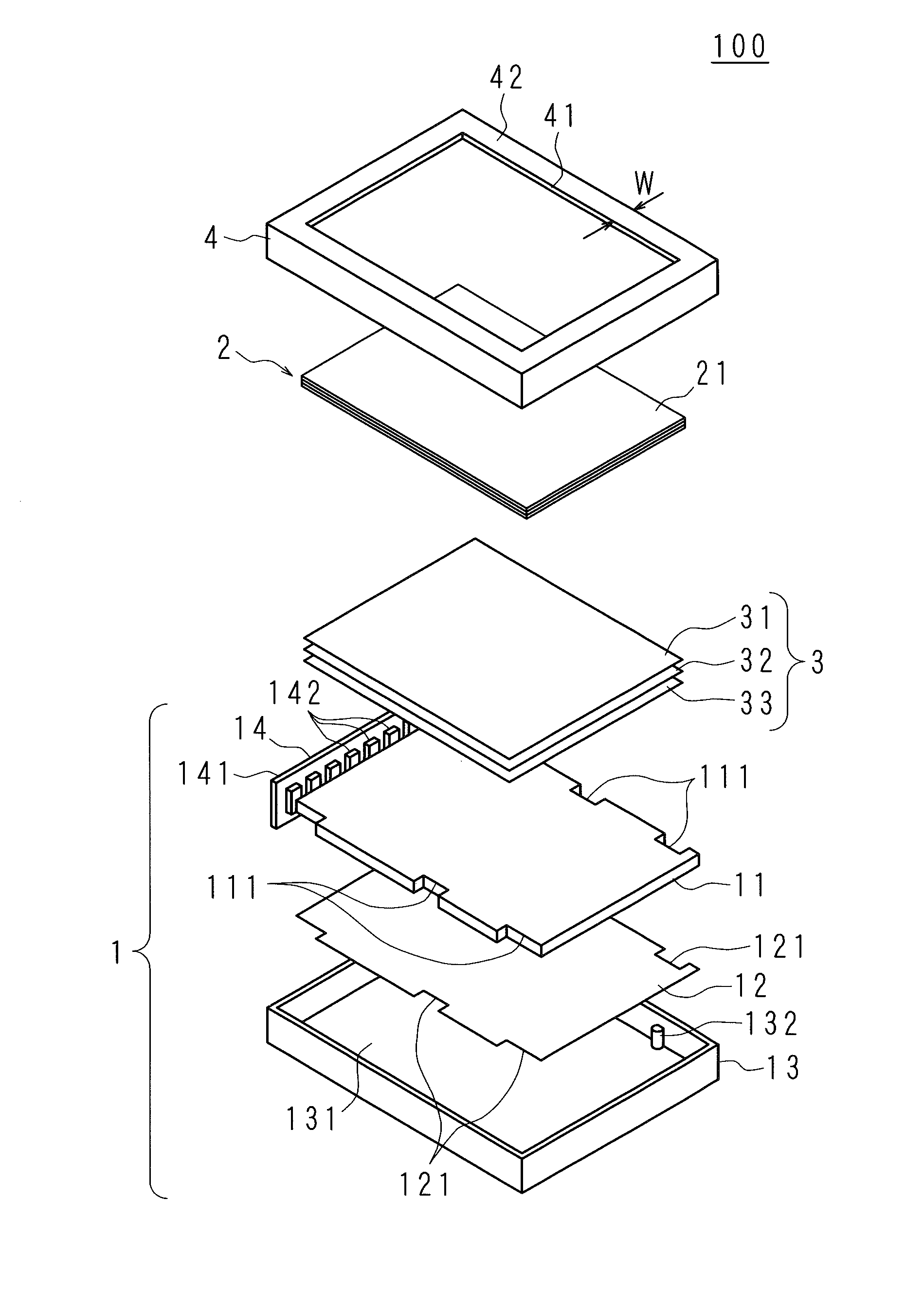
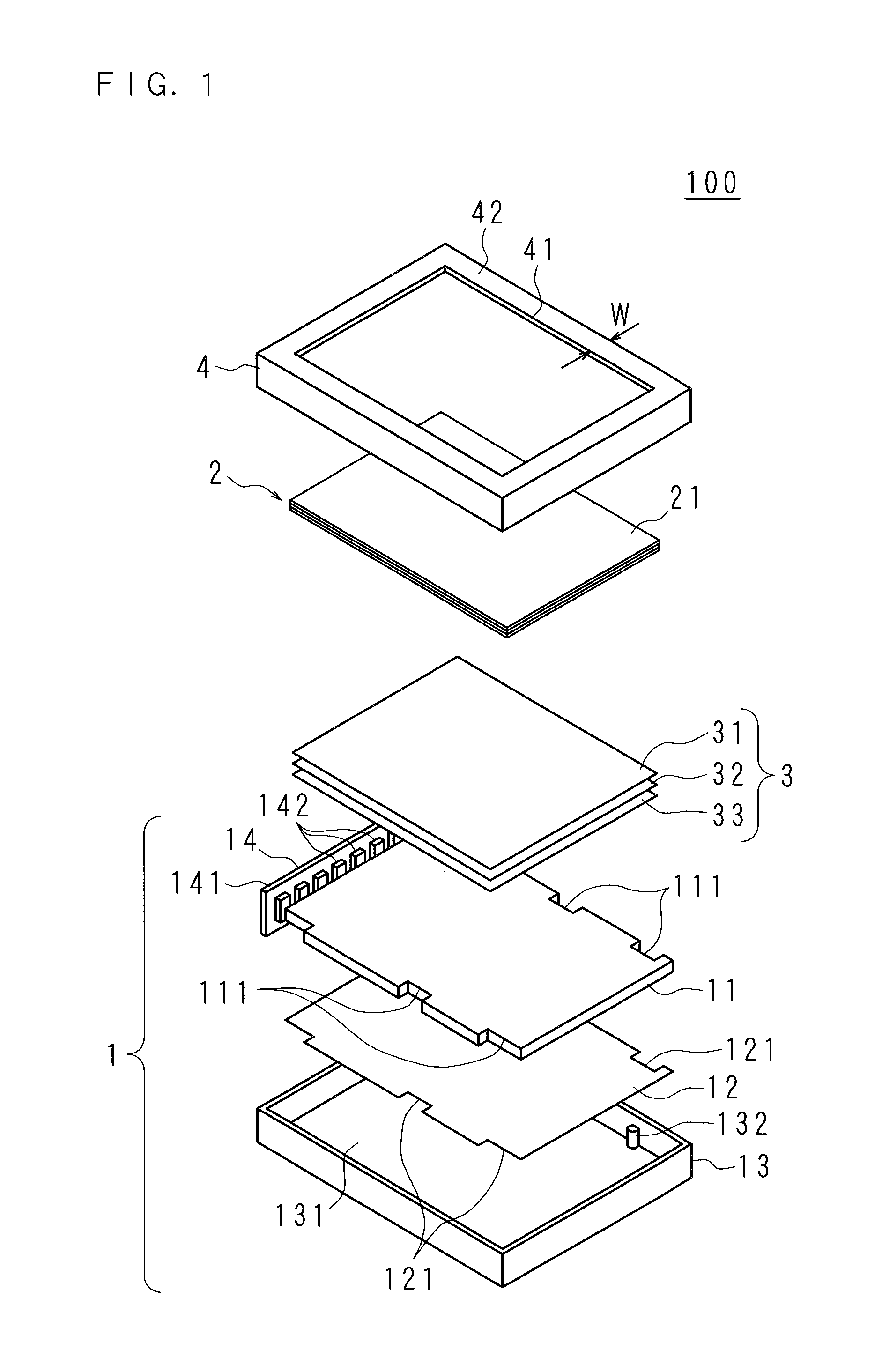
[0045]FIG. 1 is an exploded perspective view illustrating a configuration of main components of a liquid crystal television according to Embodiment 1 of the present invention. In the figure, a reference numeral 100 represents the liquid crystal television 100. As illustrated in FIG. 1, the liquid crystal television 100 includes a light source device 1, a liquid crystal display panel 2, an optical sheet 3, and a front housing part 4 which house the liquid crystal display panel 2 and the optical sheet 3 and the like.

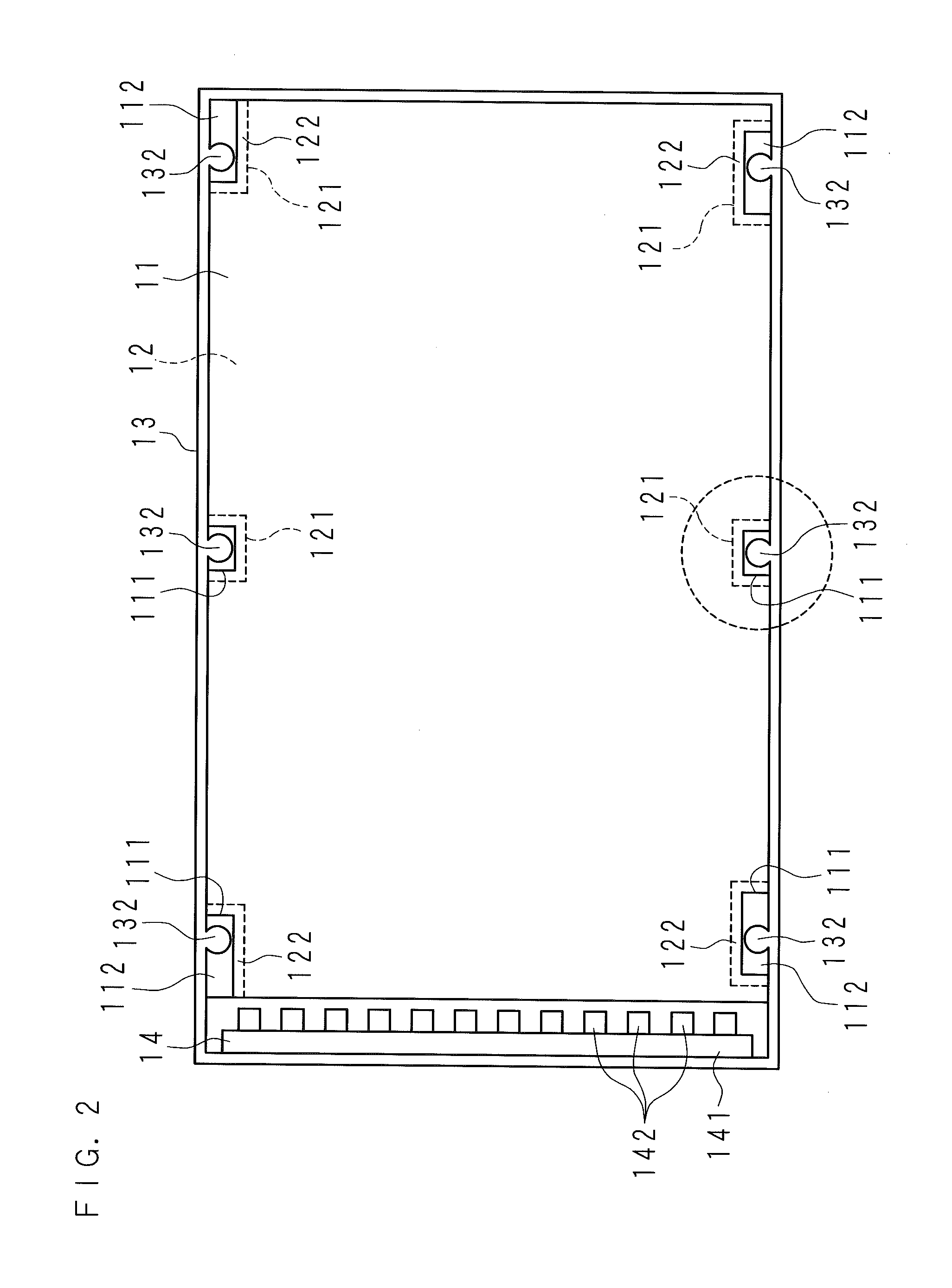
[0046]Further, the light source device 1 includes a light source unit 14, a light guide plate 11 which guides light made incident thereon from the light source unit 14 to one surface of the liquid crystal display panel 2 side, a reflection sheet 12 which reflects the light made incident from the light source unit 14 toward the one surface of the light guide plate 11, and a back housing part 13 which house the light source unit 14, the light guide plate 11 and the reflectio...

embodiment 2

[0083]A liquid crystal television 100 according to Embodiment 2 of the present invention has the same configuration as the Embodiment 1, but the configuration of a low-reflection part 123 is different therefrom. FIG. 5 is a view for describing the low-reflection part 123 of the reflection sheet 12 in the liquid crystal television 100 according to Embodiment 2 of the present invention. FIG. 5 illustrates the case in which the light guide plate 11 is eliminated in the laminating direction, and for the convenience of explanation, in order to compare with the light guide plate 11, the light guide plate 11 is shown by a broken line.

[0084]The one surface of the reflection sheet 12 facing the other surface of the light guide plate 11 is provided with the low-reflection part 123 having a reflectance lower than that of the reflection sheet 12. The low-reflection part 123 is provided along the edge of the notch part 121, and is provided so as to surround the positioning part 132 corresponding...

embodiment 3

[0097]A liquid crystal television 100 according to Embodiment 3 of the present invention has the same configuration as the Embodiment 1, but the configuration of a low-reflection part 123 is different therefrom. FIG. 6 is a view for describing the low-reflection part 123 of the reflection sheet 12 in the liquid crystal television 100 according to Embodiment 3 of the present invention. FIG. 6 illustrates the case in which the light guide plate 11 is eliminated in the laminating direction, and for the convenience of explanation, in order to compare with the light guide plate 11, the light guide plate 11 is shown by a broken line.

[0098]The one surface of the reflection sheet 12 facing the other surface of the light guide plate 11 is provided with the low-reflection part 123 having a reflectance lower than that of the reflection sheet 12. The low-reflection part 123 is provided along the edge of the notch part 121, and is provided so as to surround the positioning part 132 corresponding...


PUM


Abstract

Provided are a light source device capable of suppressing reflection of light which is irregularly reflected on a side face relating to a notch part, and a display apparatus. The light source device includes a light guide plate having a notch part formed at an edge part thereof, and a reflection sheet which is disposed to face the light guide plate and has a notch part formed at an edge part corresponding to the notch part, wherein the reflection sheet includes a low-reflection part which is provided around the notch part of a surface facing the light guide plate and has a reflectance lower than that of the reflection sheet.

Description

[0001]This application is the national phase under 35 U.S.C. §371 of PCT International Application No. PCT / JP2014 / 063728 which has an International filing date of May 23, 2014 and designated the United States of America.1. TECHNICAL FIELD[0002]The present invention relates to a light source device which includes a light guide plate having a notch part formed at an edge part, and a reflection sheet which is disposed to face the light guide plate and has a notch part formed at an edge part corresponding to the notch part of the light guide plate, and a display apparatus including the light source device.2. DESCRIPTION OF RELATED ART[0003]Recently, display apparatuses such as a liquid crystal television have been widely distributed. Many of such display apparatuses include a light guide plate, and the light guide plate irradiates a display panel which displays an image with light from a light source while propagating the light inside thereof in a plane manner. Meanwhile, it is necessar...

Claims


Application Information

Patent Timeline
IPC IPC(8): F21V8/00
CPCG02B6/0061G02B6/0045G02B6/0088G02B6/0055G02F1/133322
Inventor KUROMIZU, YASUMORI
Owner SAKAI DISPLAY PROD
Why Eureka
Try Eureka