Ignition unit for an internal combustion engine

a technology for internal combustion engines and ignition units, which is applied in the direction of spark plugs, machines/engines, x-ray tubes, etc., can solve the problems of increasing the demand for material and electrical energy for the ignition process, and achieve the effect of small volum

Active Publication Date: 2016-03-24
ROBERT BOSCH GMBH
View PDF1 Cites 6 Cited by
  • Summary
  • Abstract
  • Description
  • Claims
  • Application Information

AI Technical Summary

Benefits of technology

[0023]The space situated between the first electrode and the third electrode may be open, over a large area, toward the combustion chamber. In other words, a space situated between the electrodes has a relatively small volume compared to its coupling surface in the direction of the combustion chamber. This may be achieved, for example, with the aid of compact (e.g., cylindrical) designs of the individual electrodes. In this way, it is ensured that a large amount of gas mixture may flow around the electrodes, on the one hand, and, on the other hand, the mechanical stress on the electrodes caused by expansions of the space formed between them in the course of the ignition process is largely prevented. Depending on the embodiment of the actuator, the combustion heat may result in damage or functional impairments. Therefore, it is advantageous to provide a housing surrounding the actuator to be thermally insulating.
[0024]According to a further aspect of the present invention, an internal combustion engine including at least one combustion chamber and at least one ignition device, as has been described in detail above, is provided. According to the present invention, the three electrodes have sections within the combustion chamber, while the actuator of the ignition device is situated outside the combustion chamber. In this way, the actuator may be protected against the thermal, chemical, and mechanical stress within the combustion chamber.

Problems solved by technology

This increases the demand for material and electrical energy for the ignition process, however.

Method used


Image

  • Ignition unit for an internal combustion engine
  • Ignition unit for an internal combustion engine
  • Ignition unit for an internal combustion engine

Examples


Embodiment Construction

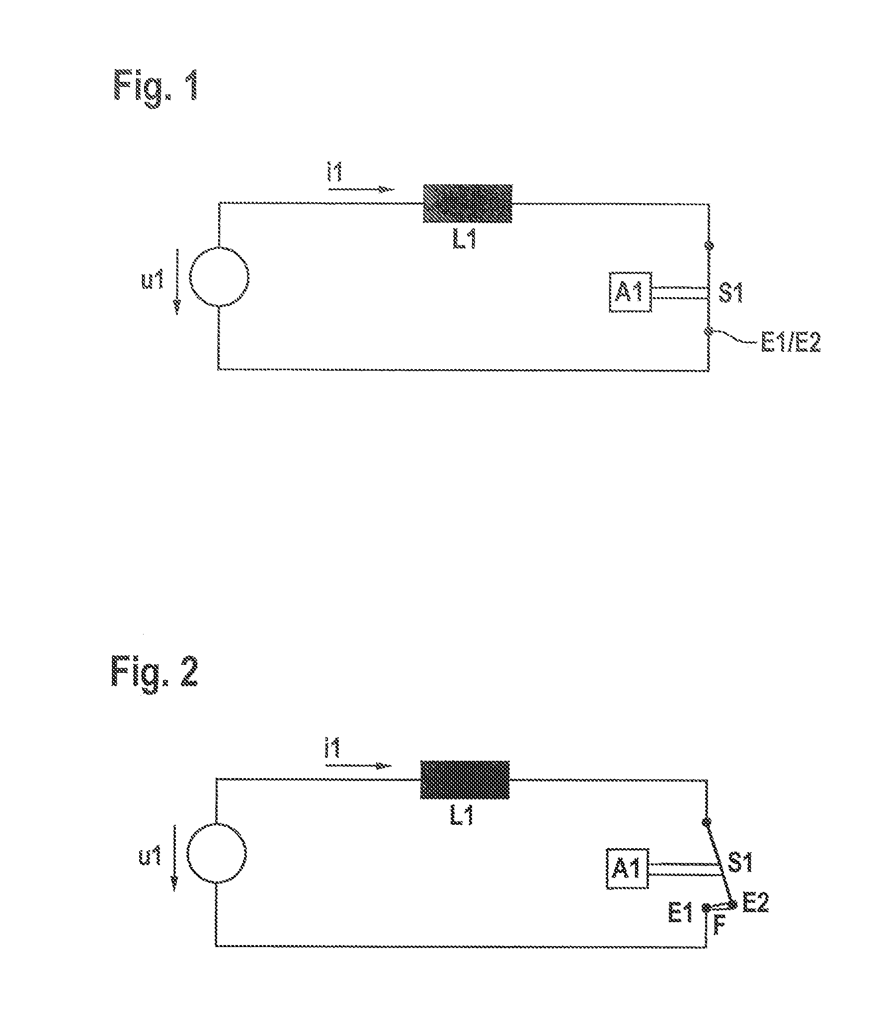
[0035]FIG. 1 shows an electrical energy source u1, which is configured to drive a current i1 with the aid of an inductor L1. For this purpose, a switch S1 downstream from inductor L1 is closed to ground with the aid of an actuator A1. Switch S1 includes a first electrode E1 and a second electrode E2. In FIG. 1, the two electrodes E1, E2 are in electrical contact with one another. Inductor L1 is charged with magnetic energy with the aid of current flow i1.

[0036]FIG. 2 shows the system represented in FIG. 1 after switch S1 has been opened with the aid of actuator A1. Due to the fact that switch S1 is now open, an ignition spark F has formed between electrodes E1 and E2, which are now spatially separated from one another. Its energy is provided by the magnetic field of inductor L1. If switch S1 or the system of electrodes E1, E2 is situated within a combustion chamber II and ignitable mixture is situated in the area of ignition spark F, the ignition spark may be used to ignite the mixt...


PUM


Abstract

An ignition device for a combustion chamber of an internal combustion engine includes a first electrode and a second electrode, which is movable with the aid of an actuator. The ignition device is configured to generate a first ignition spark when a contact between the first and second electrode is interrupted. To accomplish this, the second electrode is moved away from the first electrode. A third electrode is also provided, which is spaced apart from the first electrode. With the aid of the third electrode, a second ignition spark can be generated by moving the second electrode away from the other two electrodes. With the three electrodes, the ignition unit is configured to allow the two ignition sparks to pass through a volume formed between the electrodes in the direction transverse to the longitudinal extension of the ignition sparks in the course of the movement of the second electrode.

Description

FIELD OF THE INVENTION[0001]The present invention relates to an ignition unit for an internal combustion engine. In particular, the present invention relates to an improved electrode system to be arranged within a combustion chamber of an internal combustion engine.BACKGROUND INFORMATION[0002]Ignition units for spark-ignition internal combustion engines are known from the related art. Electrical energy, which is often temporarily stored with the aid of an inductor, flashes through the combustion chamber volume between two electrodes, whereby the ignitable mixture in the combustion chamber is ignited. The two electrodes are usually fixedly situated relative to one another. A spark gap between the electrodes, which is also fixed, is therefore predefined. In order to enable the mixture to be successfully ignited, an at least partially ignitable mixture must be present in the area of the ignition spark gap, the location of which varies only in a stochastically distributed way. The tende...

Claims


Application Information

Patent Timeline
Patent Type & Authority Applications(United States)
IPC IPC(8): H01T13/46F02P15/08H01T13/24
CPCH01T13/462H01T13/24F02P15/08H01T13/42
Inventor SENFTLEBEN, HARTWIGVOGEL, MANFRED
Owner ROBERT BOSCH GMBH
Why Eureka
Try Eureka