
Electric machine stator lamination with dual phase magnetic material

a technology of magnetic material and electric machine, which is applied in the manufacture of stator/rotor bodies, applying/manufacturing slot closures, windings, etc., can solve the problems of large mechanical loss and manufacturing challenges, and achieve the effects of improving electric machine component design, performance and manufacturability, and high efficiency

Active Publication Date: 2016-03-24
GENERAL ELECTRIC CO
View PDF12 Cites 5 Cited by
  • Summary
  • Abstract
  • Description
  • Claims
  • Application Information

AI Technical Summary

Benefits of technology

This patent describes a way to make an electric machine stator lamination that is lighter, faster, and more efficient. This means that the lamination has a special material that allows for a better magnetic performance. This results in a smaller and less expensive electric machine that can achieve higher speeds and power.

Problems solved by technology

As a result, a large amount of mechanical loss may be created from the windage or churning of the fluid and / or gas within the air gap between the rotor and stator.
Manufacturing challenges remain with the installation of wedges in the slot closures.

Method used


Image

  • Electric machine stator lamination with dual phase magnetic material
  • Electric machine stator lamination with dual phase magnetic material
  • Electric machine stator lamination with dual phase magnetic material

Examples


Embodiment Construction

[0018]Unless defined otherwise, technical and scientific terms used herein have the same meaning as is commonly understood by one of ordinary skill in the art with respect to the presently disclosed subject matter. The terms “first”, “second”, and the like, as used herein do not denote any order, quantity, or importance, but rather are used to distinguish one element from another. The terms “a”, “an”, and “the” do not denote a limitation of quantity, but rather denote the presence of at least one of the referenced item, and the terms “front”, “back”, “bottom”, and / or “top”, unless otherwise noted, are used for convenience of description only, and are not limited to any one position or spatial orientation.

[0019]If ranges are disclosed, the endpoints of all ranges directed to the same component or property are inclusive and independently combinable (e.g., ranges of “up to about 25 wt. %,” is inclusive of the endpoints and all intermediate values of the ranges of “about 5 wt. % to abou...


PUM


Abstract

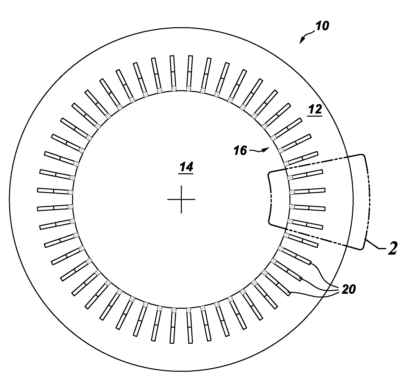
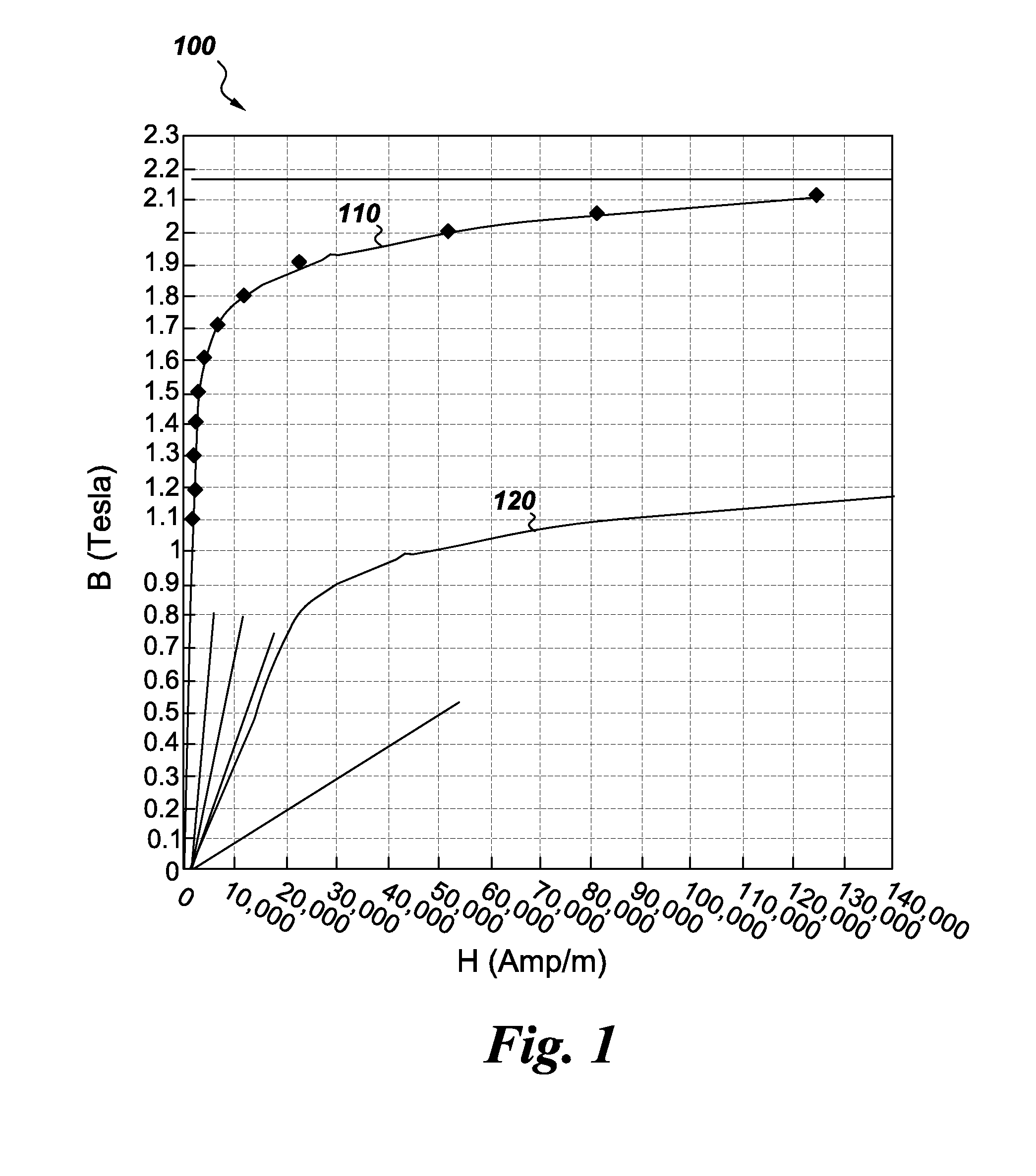
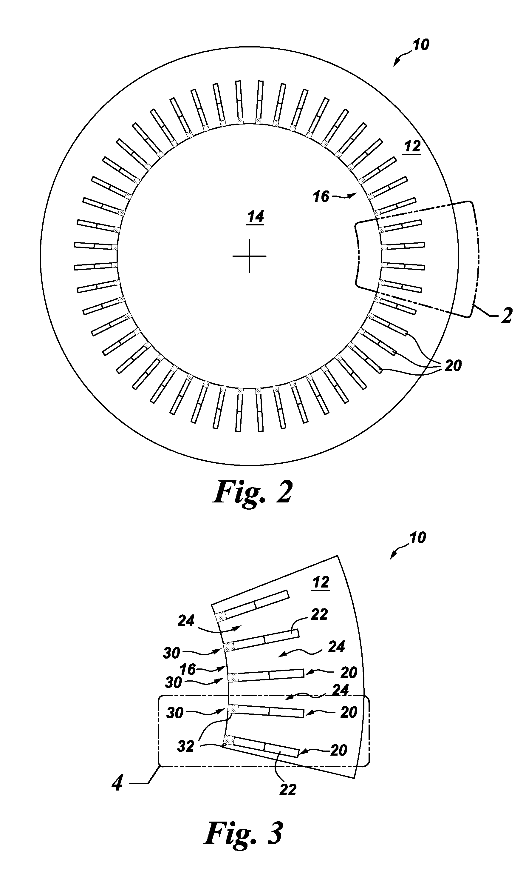
A stator lamination for an electric machine has a circular lamination with an annular bore therethrough; winding slots therethrough; and, slot closures disposed adjacent to the winding slots. The stator lamination is formed of a dual magnetic phase material, such that the magnetic property of the lamination can have a first state and a magnetic property in a second state, wherein the second state is different than the first state. The slot closures regions are treated so as to transition to the second state. A method of manufacturing an electric machine component is also disclosed.

Description

CROSS REFERENCE TO RELATED APPLICATIONS[0001]This Continuation-In-Part (C.I.P.) application claims priority to the Feb. 28, 2013 filing date of U.S. application Ser. No. 13 / 780,773, Entitled: DUAL MAGNETIC PHASE STATOR LAMINATIONS FOR STATOR PERMANENT MAGNET ELECTRIC MACHINES (attorney docket no. 263233-1). This C.I.P. application also claims priority to the Mar. 29, 2013 filing date of U.S. application Ser. No. 13 / 853,122, Entitled: DUAL MAGNETIC PHASE ROTOR LAMINATIONS FOR INDUCTION MACHINES (attorney docket no. 264829-2) which, in turn, claims priority to the Mar. 14, 2013 filing date of U.S. Provisional Application Ser. No. 61 / 785,020, Entitled: DUAL MAGNETIC PHASE ROTOR LAMINATIONS FOR INDUCTION MACHINES (attorney docket no. 264829-1). The contents of all are incorporated herein by reference in their entirety.GOVERNMENT LICENSE RIGHTS[0002]The invention was made with Government support under contract number DE-EE0005573 awarded by the United States Department of Energy. The Gov...

Claims


Application Information

Patent Timeline
IPC IPC(8): H02K3/493H02K3/28H02K15/00H02K15/02
CPCH02K3/493H02K15/02H02K15/0018H02K3/28
Inventor GALIOTO, STEVEN, JOSEPHEL-REFAIE, AYMAN, MOHAMED, FAWZI
Owner GENERAL ELECTRIC CO
Learn More