Power overload protection using hiccup mode

a technology of overload protection and power converter, applied in the direction of electric variable regulation, process and machine control, instruments, etc., can solve the problems of auxiliary transformers being more complex and expensive to install, auxiliary transformers being more expensive to install, and not providing as good regulation as opto-couplers

Active Publication Date: 2016-03-24
MURATA MFG CO LTD
View PDF5 Cites 13 Cited by
  • Summary
  • Abstract
  • Description
  • Claims
  • Application Information

AI Technical Summary

Benefits of technology

[0014]In the converter, when the second sense circuit detects an overload current, the switch controller may reduce the duty cycle of the switch, causing the error signal to saturate.

Problems solved by technology

Opto-couplers provide tight voltage and current regulation properties, but are more complex and costly to install than auxiliary transformers.
Auxiliary transformers on the other hand, while not providing as good regulation as opto-couplers, are less costly and tend to be more reliable in long term operation.
By repeatedly switching off and restarting the converter circuit, the hiccup mode results in greatly reduced power loss.
In a primary side regulated converter, where voltage feedback is provided by an auxiliary winding, hiccup mode of operation is not however possible because imperfect cross regulation prevents the voltage on the feedback winding from reducing when the output load is high and the auxiliary load is low.
However, these methods are costly and can lead to complex circuit designs.

Method used


Image

  • Power overload protection using hiccup mode
  • Power overload protection using hiccup mode
  • Power overload protection using hiccup mode

Examples


first preferred embodiment

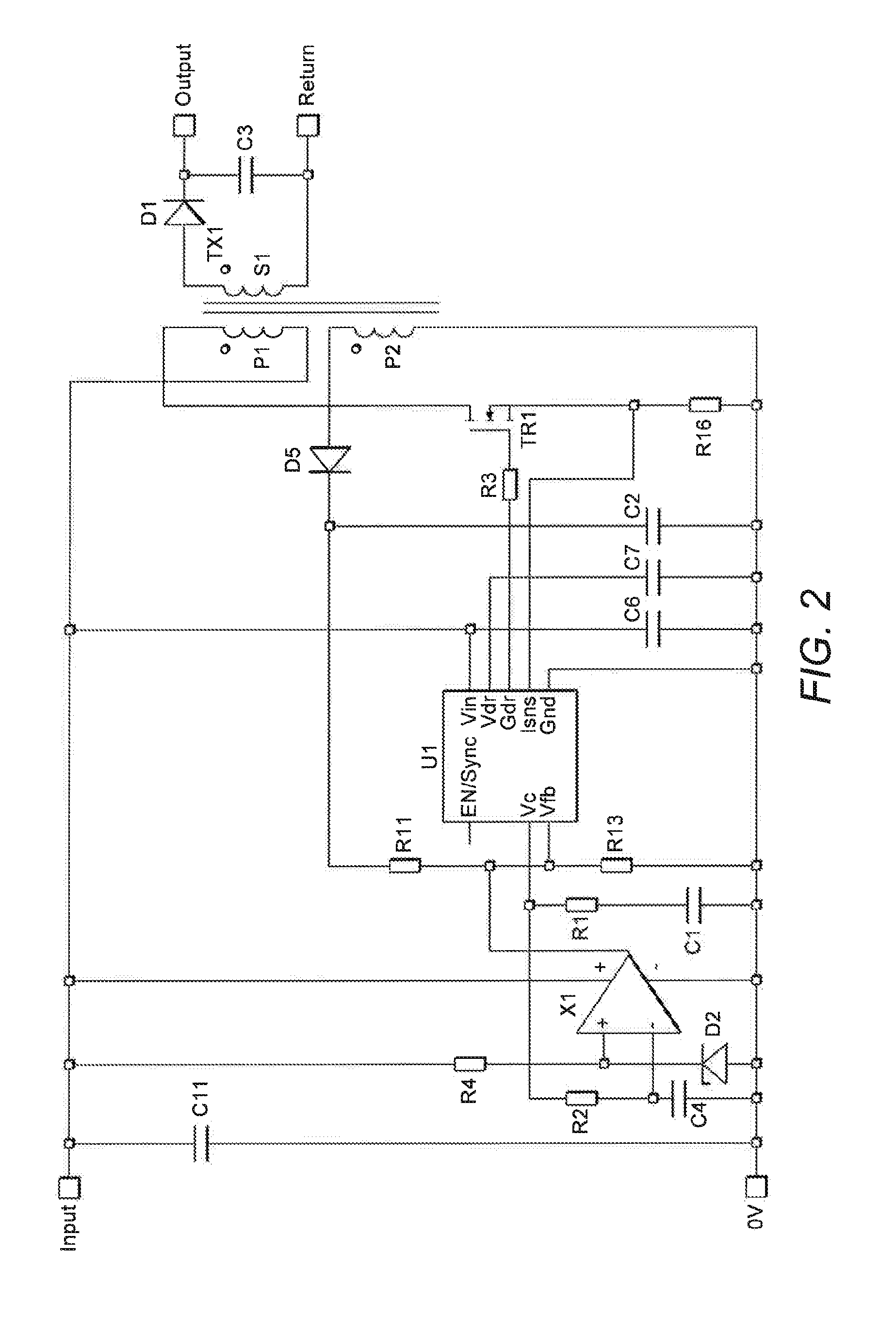
[0038]A first preferred embodiment of the present invention will now be described with reference to FIG. 2.

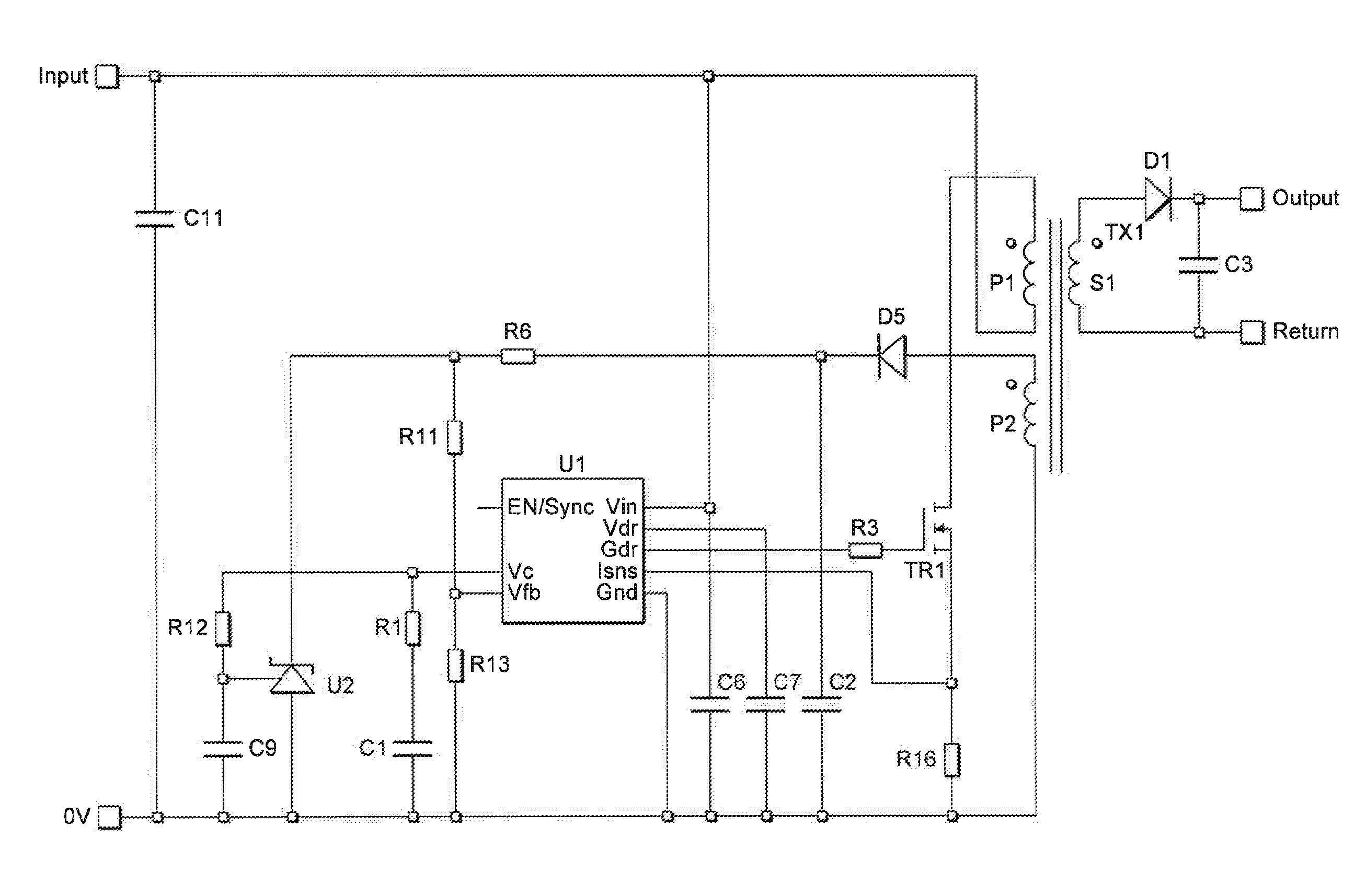
[0039]The circuit in FIG. 2 shows a primary side regulated flyback power supply circuit including auxiliary primary side transformer winding P2. As before, switching circuit is implemented using a switching MOSFET TR1 and a PWM Controller U1. The drain terminal of the MOSFET TR1 connects to one side of the primary transformer winding P1, while the source of MOSFET TR1 connects to the 0 V voltage rail. As is known in the art, the operation of the switching MOSFET TR1 is controlled by signal output from the PWM controller U1. Specifically, the Gate Drive terminal Gdr of the PWM controller U1 is connected to the gate of the switching MOSFET TR1, so that the MOSFET TR1 can be switched on and off as desired to control the energizing of the primary coil P1. The ground terminal Gnd of the PWM controller U1 is connected to the low voltage rail (0 V). The operation of the controller is ...


PUM


Abstract

A DC-to-DC converter includes a transformer including a primary transformer coil connected to a power input terminal; a secondary transformer coil connected to a power output terminal; a switching circuit including a first sense circuit that detects a voltage condition of the transformer, the voltage received at the first sense circuit being used to regulate the duty cycle of the switch and to initiate a hiccup mode that dissipates power in the primary and/or secondary windings when the voltage condition detected at the first sense circuit indicates an overload of the transformer; a second sense circuit that detects an over-current condition at the switch and/or primary winding; and a further feedback path connected between the second sense circuit and the first sense circuit that provides a second signal to the first sense circuit to boost the first signal when an overload is detected, and to initiate the hiccup mode.

Description

BACKGROUND OF THE INVENTION[0001]1. Field of the Invention[0002]The present invention relates to a power converter, and in particular to a power converter including an overload protection function known as a hiccup mode.[0003]2. Description of the Related Art[0004]In a flyback converter, the input and output sides of the circuit are isolated from one another via the primary and secondary coils of a transformer. To ensure reliable operation of the converter, a control signal indicating the voltage or current condition of the transformer is passed from the output side of the converter control circuit to the input side, so that the switching of the primary and second transformer coils can be properly regulated. Converter control circuits typically operate according to voltage mode control or current mode control, depending on the type of control signal that is used, a voltage sense signal or a current sense signal, for example.[0005]Both control methods require a signal related to the ...

Claims


Application Information

Patent Timeline
Patent Type & Authority Applications(United States)
IPC IPC(8): H02M3/335H02M1/00H02M1/32
CPCH02M3/33546H02M2001/0003H02M1/32H02M1/08H02M3/33507H02H3/06H02H7/1213H02M1/0003
Inventor WARNES, FRANK
Owner MURATA MFG CO LTD
Why Eureka
Try Eureka