DC-DC converter and its control method, and switching regulator and its control method

a technology of dc-dc converter and control method, applied in the direction of electric variable regulation, process and machine control, instruments, etc., can solve the problems of increasing power consumption and heat generation in the entire system, excessive power spent in the conversion of a voltage in both regulators, etc., and achieve the effect of preventing the inversion of the polarity of the error signal

Inactive Publication Date: 2007-03-08
MONTEREY RES LLC
View PDF11 Cites 6 Cited by
  • Summary
  • Abstract
  • Description
  • Claims
  • Application Information

AI Technical Summary

Benefits of technology

[0017] In the control method of the DC-DC converter and the switching regulator of the invention, if the first voltage is nearly zero right after turning on the power source, an error signal having normal polarity can be generated. Hence, inversion of polarity of the error signal can be prevented.

Problems solved by technology

However, in the voltage generating circuit in Japanese unexamined patent publication No. 2002-111470, since linear regulators are used in both regulators 111 and 112, excessive power is spent in conversion of a voltage in both regulators.
Such electric power by conversion of a voltage is a problem because it causes increase of power consumption and heat generation in the entire system.

Method used


Image

  • DC-DC converter and its control method, and switching regulator and its control method
  • DC-DC converter and its control method, and switching regulator and its control method
  • DC-DC converter and its control method, and switching regulator and its control method

Examples


embodiment 1

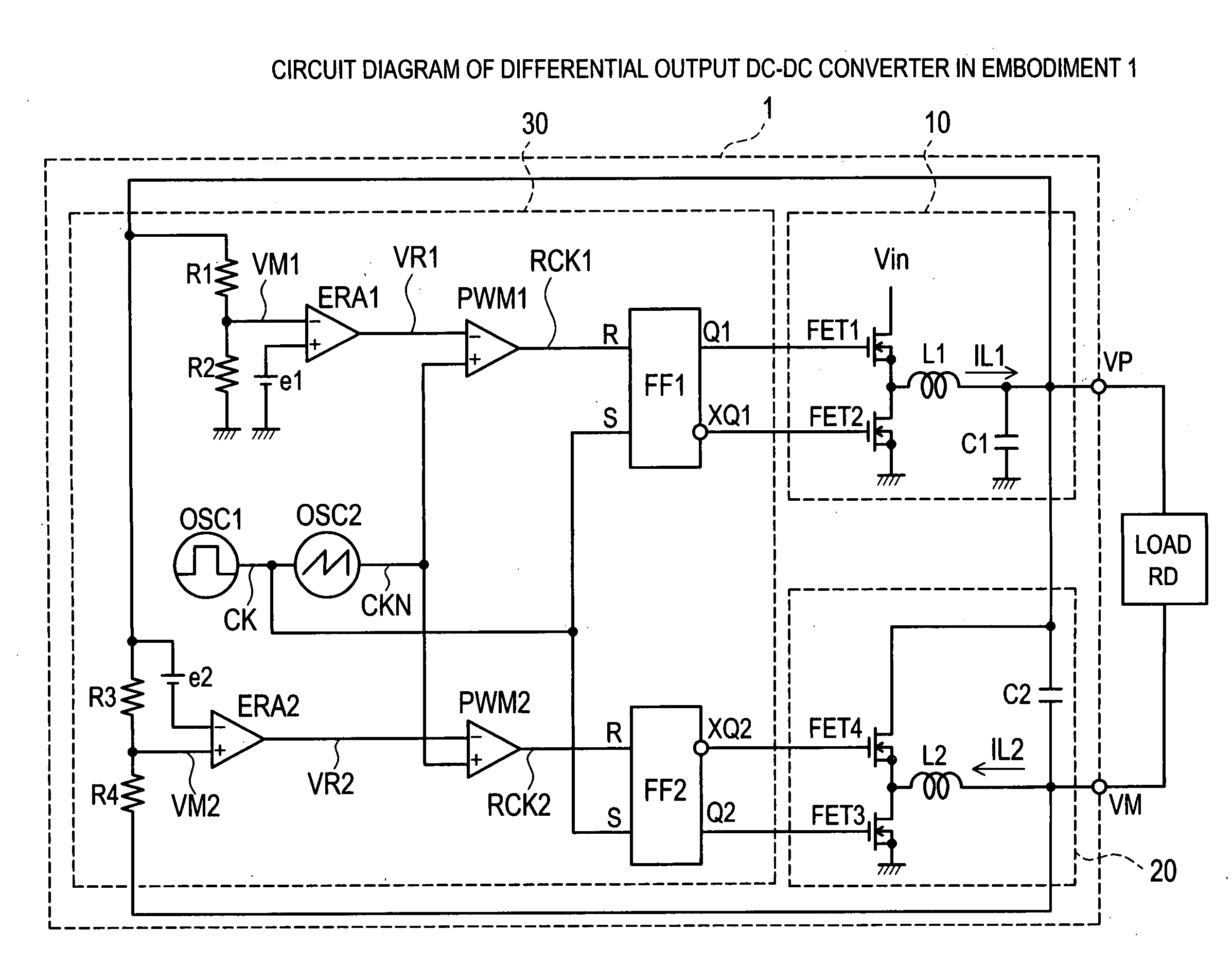
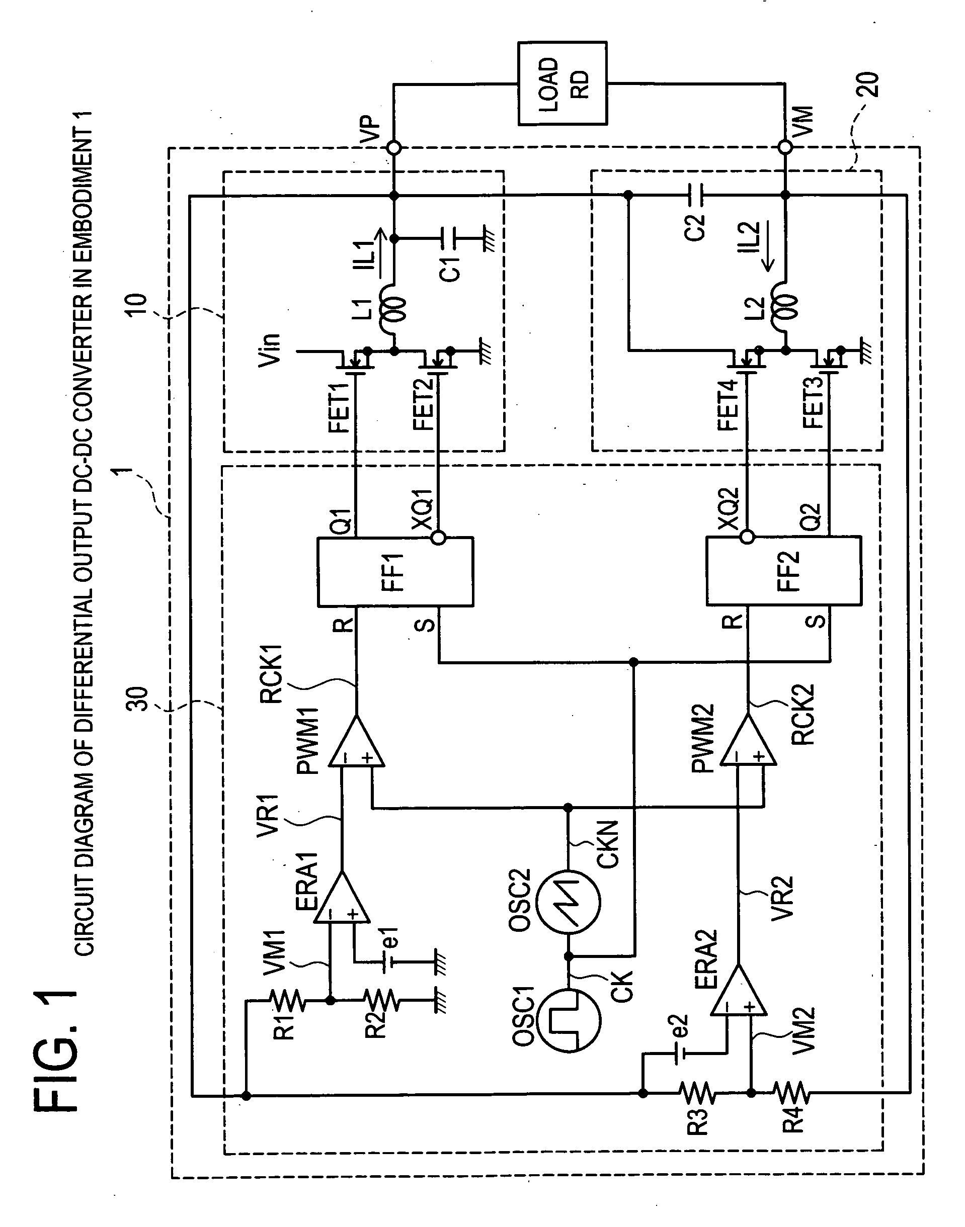
[0024]FIG. 1 is a circuit diagram of a differential output DC-DC converter 1 in an embodiment 1 of the invention.

[0025] The differential output DC-DC converter 1 is a DC-DC converter for converting an input voltage V0 applied to a power supply terminal Vin into two sets of different output voltages V1 and V2, and issuing to output terminals VP and VM. The differential output DC-DC converter 1 comprises a first switching regulator 10 of a current source type, a second switching regulator 20 of a current sink type, and a control unit 30 for controlling the first switching regulator 10 and the second switching regulator 20.

[0026] The first switching regulator 10 includes a first transistor FET1 as a main switch, a second transistor FET2 as a synchronous rectifying circuit, a choke coil L1 as a main inductor, and a capacitor C1 as a smoothing capacitor. In the first transistor FET1 and the second transistor FET2, their source electrodes are connected to a power supply terminal Vin and...

embodiment 2

[0050]FIG. 3 is a circuit diagram of a differential output DC-DC converter 1A in an embodiment 2. The differential output DC-DC converter 1A operating in a current mode comprises a first switching regulator 10A of a current source type, a second switching regulator 20A of a current sink type, and a control unit 30A for controlling the first switching regulator 10A and the second switching regulator 20A.

[0051] The first switching regulator 10A is similar to a first switching regulator 10 of an embodiment 1, except that a sense resistance Rs1 is provided between a choke coil L1 and an output terminal VP. This sense resistance Rs1 converts a current IL1 flowing in the choke coil L1 into a voltage generated at both ends, and detects.

[0052] The second switching regulator 20A is similar to a second switching regulator 20 of an embodiment 1, except that a sense resistance Rs2 is provided between a choke coil L2 and an output terminal VM, and that a source electrode side of a fourth trans...

embodiment 3

[0055]FIG. 4 is a circuit diagram of a differential output DC-DC converter 1B in an embodiment 3. The differential output DC-DC converter 1B operating in a current mode comprises a first switching regulator 10B of a current source type, a second switching regulator 20B of a current sink type, and a control unit 30B for controlling the first switching regulator 10B and the second switching regulator 20B.

[0056] The first switching regulator 10B is similar to a first switching regulator 10 of an embodiment 1, except that a sense resistance Rs1 is provided between a choke coil L1 and an output terminal VM, and that a first diode D1 as an asynchronous rectifying circuit is provided instead of a second transistor FET2 as a synchronous rectifying circuit. This sense resistance Rs1 converts a current IL1 flowing in the choke coil L1 into a voltage generated at both ends, and detects.

[0057] The second switching regulator 20B is similar to a second switching regulator 20 of the embodiment 1...


PUM


Abstract

A differential output DC-DC converter capable of decreasing power consumption is presented. The differential output DC-DC converter 1 comprises output terminals VP and VM connected to both ends of load, and a switching regulator 10 for passing a source current. It further comprises a third transistor FET3, a choke coil L2, and a fourth transistor FET4 for rectifying a sink current in a flowing direction, and further a second regulator for allowing the sink current to flow, and issuing a voltage higher than a grounding point GND voltage and lower than a voltage of an output terminal VP, to an output terminal VM.

Description

CROSS-REFERENCE TO RELATED APPLICATIONS [0001] This application is based upon and claims the benefit of priority from each of the prior Japanese Patent Application No. 2005-256419 filed on Sep. 5, 2005, the entire contents of which are incorporated herein by reference. BACKGROUND OF THE INVENTION [0002] 1. Field of the Invention [0003] The present invention relates to a DC-DC converter for issuing a differential voltage, and a switching regulator for passing sink current. [0004] 2. Description of the Related Art [0005] Along with diversification of an operating voltage in electronic devices, there is an increasing demand for a DC-DC converter for generating different supply voltages. Recently, for application into interface technology between electronic devices of different supply voltages, not only at the high voltage side of supply voltage but also at the low voltage side, the DC-DC converter issuing differential voltage by setting variably is being demanded. [0006] One of such in...

Claims


Application Information

Patent Timeline
Patent Type & Authority Applications(United States)
IPC IPC(8): G05F1/00
CPCH02M3/1584Y02B70/1466H02M3/1588Y02B70/10A47J47/04B65D85/70B65D90/0066
Inventor HASEGAWA, MORIHITOOZAWA, HIDEKIYO
Owner MONTEREY RES LLC
Why Eureka
Try Eureka