Tibial Tubercule Osteotomy

a tubercule and osteotomy technology, applied in the field of tibial tubercule osteotomy, can solve the problems of mass production of commercially available systems and complicated use, and achieve the effect of promoting bone in-growth and reducing patellofemoral conditions

Active Publication Date: 2016-03-31
BIOMET MFG CORP
View PDF43 Cites 8 Cited by
  • Summary
  • Abstract
  • Description
  • Claims
  • Application Information

AI Technical Summary

Benefits of technology

[0053]As shown in FIG. 10, after the tubercle flap 330 has been generated, the method comprises repositioning the tubercle flap 330 in an anterior direction or in both anterior and medial-lateral directions to form a gap 338 between the tubercle flap 330 and three resected surfaces 332, 334, 336 of the tibia 104. The hinge bore or stress relief hole 322 ensures that repositioning the tubercle flap 330 does not crack or splinter the tibia 104. The tubercle flap 330 is repositioned to a location predetermined during the pre-operative planning stage. Repositioning the tubercle flap 132 alters the position of the patient's patella remove a pain-causing load and results in alleviation of a patellofemoral condition characterized by malalignment of the patella relative to asymptomatic individuals. After repositioning the tubercle flap 330 the method comprises implanting or positioning a patient specific implant or wedge 200a, 200b in gap 338, as shown in FIGS. 6A, 6B, and 11. As described above, the patient-specific implant 200a, 200b has a predetermined shape configured during the pre-operative planning stage. The implant 200a, 200b comprises a first portion 202, and optionally a second portion 206 or a second 206 and third portion 210. In some embodiments, the patient-specific implant 200a, 200b is composed of a material that promotes bone in-growth. When the second implant 200b is used, the spherical portion 214 is positioned in the stress relief hole 322. In an alternative method, the implant is an off-the-shelf, i.e., non-patient-specific, implantable wedge. Optionally, the method comprises securing the tubercle flap 330 by driving a screw 340 through the tubercle flap 330 and the wedge 200a, 200b, and into the tibia 104 through one of the resected surface 332. The wedge 200a, 200b maintains the position of the repositioned tubercle flap 330 relative to the tibia 104 and prevents the tubercle flap 330 from reverting to its original location.

Problems solved by technology

However, these systems generally comprise multiple units that are complicated to use.
Moreover, the commercially available systems are mass produced, and are not tailored to a specific patient's anatomy.

Method used


Image

  • Tibial Tubercule Osteotomy
  • Tibial Tubercule Osteotomy
  • Tibial Tubercule Osteotomy

Examples


Embodiment Construction

[0026]Example embodiments will now be described more fully with reference to the accompanying drawings.

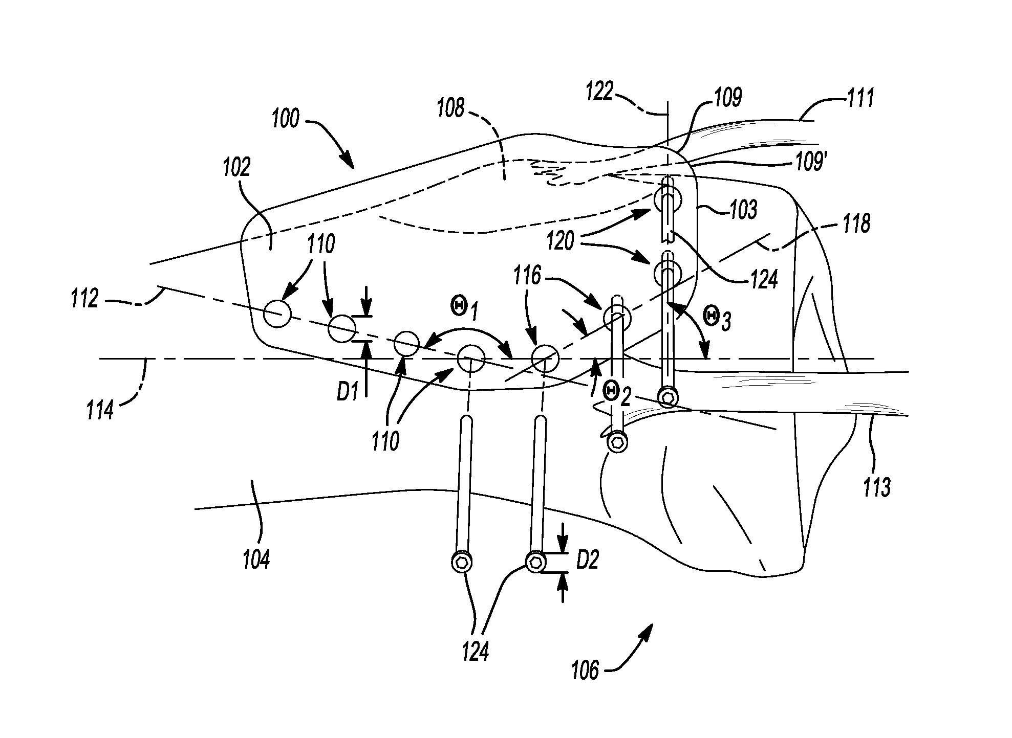
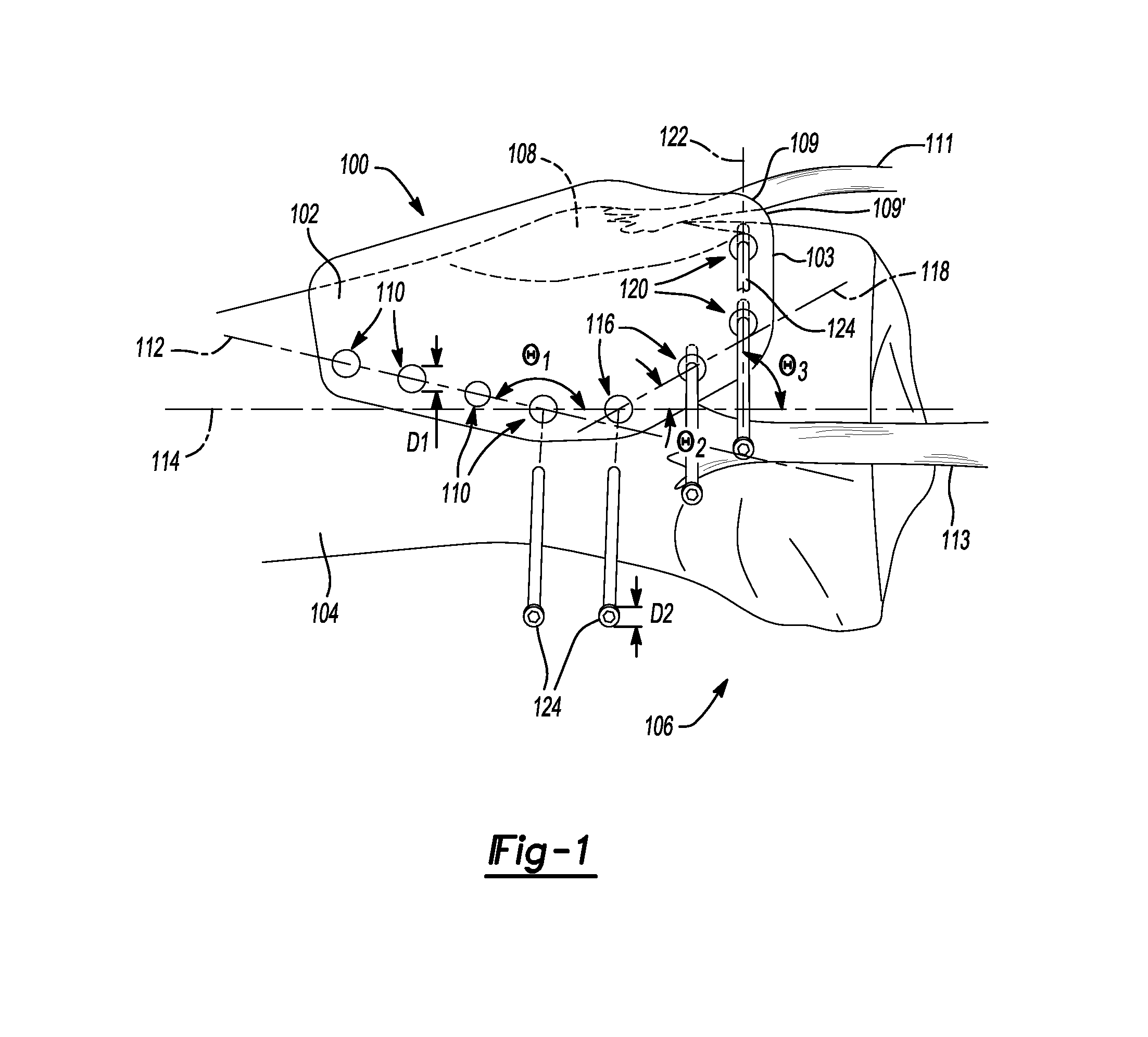
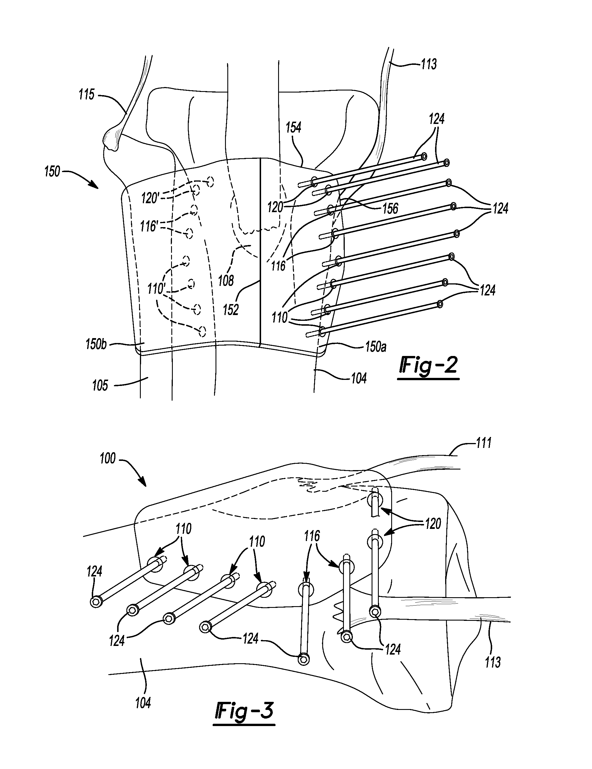
[0027]The present teachings generally provide patient-specific tibial tubercle osteotomy guides that include a guide body defining a portion with a bone-engaging surface that conforms as a negative surface to a corresponding surface of a specific patient's tibia about the patient's tibial tubercle, and a guide portion that guides a surgical instrument to a specific location on the specific patient's tibia, wherein the bone-engaging surface and guide portion are configured during a pre-operative planning stage, in which a medical professional determines the location of a tibial tubercle osteotomy and amount of correction needed. In various embodiments, the guide body further defines a soft tissue engaging surface, wherein the soft tissue-engaging surface is configured during the pre-operative planning stage of a tibial osteotomy to conform as a negative surface to a corresponding su...


PUM


Abstract

Patient-specific guides for a tibial tubercle osteotomy are provided. The guides include a guide body defining a portion with a bone-engaging surface that conforms as a negative surface to a corresponding surface of a specific patient's tibia, and a guide portion that guides a surgical instrument to a specific location on the specific patient's tibia, wherein the bone-engaging surface and guide portion are configured during a pre-operative planning stage. Methods for performing a tibial tubercle osteotomy with the patient-specific guides are also provided.

Description

BACKGROUND[0001]This section provides background information related to the present disclosure which is not necessarily prior art.[0002]A tibial tubercle osteotomy is a surgical procedure which is performed to treat patellofemoral conditions, such as patellar instability, patellofemoral pain and chondrosis, and osteoarthritis. Such an osteotomy is typically performed when nonoperative measures, such as physical therapy, have failed. During a tibial tubercle osteotomy an incision is made in the anterior of a patient's leg just inferior to the patella, and a proximal and anterior portion of a tibia is partially resected to generate a tubercle flap. The tubercle flap is then repositioned in anterior and medial-lateral directions and held in place with screws. Typically, a tibial tubercle osteotomy results in anteromedialization (AMZ) of the tubercle. This repositioning alters the position of the patella in a patient to remove a pain-causing load, resulting in alleviation of a patellofe...

Claims


Application Information

Patent Timeline
Patent Type & Authority Applications(United States)
IPC IPC(8): A61B17/17A61B17/15A61B17/80
CPCA61B17/1764A61B17/8095A61B17/151A61B2017/564A61B2017/568A61F2002/2892A61B17/152
Inventor MAXSON, WILLIAM
Owner BIOMET MFG CORP
Why Eureka
Try Eureka