Eureka AIR delivers breakthrough ideas for toughest innovation challenges, trusted by R&D personnel around the world.

Method and apparatus for taped interlayer flow cell with masking and conductive traces

Inactive Publication Date: 2016-03-31
CORNING INC
View PDF10 Cites 2 Cited by
  • Summary
  • Abstract
  • Description
  • Claims
  • Application Information

AI Technical Summary

Benefits of technology

The present invention provides a flow cell comprising a substrate with a metal layer on one surface and a tape layer with flow channels adhered to the substrate. A second substrate with another metal layer on one surface is adhered to the tape layer opposite the first substrate. The metal layers have cutouts to expose the flow channels. The method for fabrication involves depositing a metal layer on a substrate, adhering a tape layer with flow channels, etching or forming the metal layer with cutouts, providing a mating substrate with a second metal layer, aligning and bonding the mating substrate with the tape layer. The technical effects include enhanced precision in flow channel alignment and improved cell performance with reduced pressure drop and flow channel blockage.

Problems solved by technology

Such devices are generally expensive, inflexible, and difficult to construct.
Conventional flow cell fabrication via molding, etching, and bonding is more expensive (both in required tooling and processing) and has longer lead time.
In many cases, bonding methods to enclose the flow cell require high temperatures which prevent the use of many surface coatings and the encapsulation fluids or live cultures.
For prior art involving tape, no prior art fabrication methods provide capability for high precision formation of the flow channels.
Additionally, imperfections in the tape as adhered to the substrates is aesthetically displeasing.
In applications where the tape bonding to the substrates does not provide sufficient sealing no prior art technique is available to economically provide such sealing.
Finally, the prior art fabrication methods with tape cannot be accomplished on wafer level processing due to issues dicing the components on a wafer containing a tape layer.

Method used


Image

  • Method and apparatus for taped interlayer flow cell with masking and conductive traces
  • Method and apparatus for taped interlayer flow cell with masking and conductive traces
  • Method and apparatus for taped interlayer flow cell with masking and conductive traces

Examples


Embodiment Construction

[0027]Embodiments disclosed herein provide methods and apparatus for fabricating a taped interlayer flow cell. None of the prior art use a laser to obtain high precision, have a metallization layer to hide the imperfections in the tape, use a removable tape (UV release), or combine a standard well with a room temperature bonded edges to obtain better channel dimensional properties or a fast customization of the flow cell. Use of UV or thermally releasable tape also allows the flow cell to be easily disassembled, which may be advantageous for certain applications. Also, adding electrical leads to the flow cell is a challenge and normally accomplished with external leads. Finally, the prior art fabrication methods with tape cannot be done on wafer level processing due to issues dicing the components on a wafer containing a tape layer.

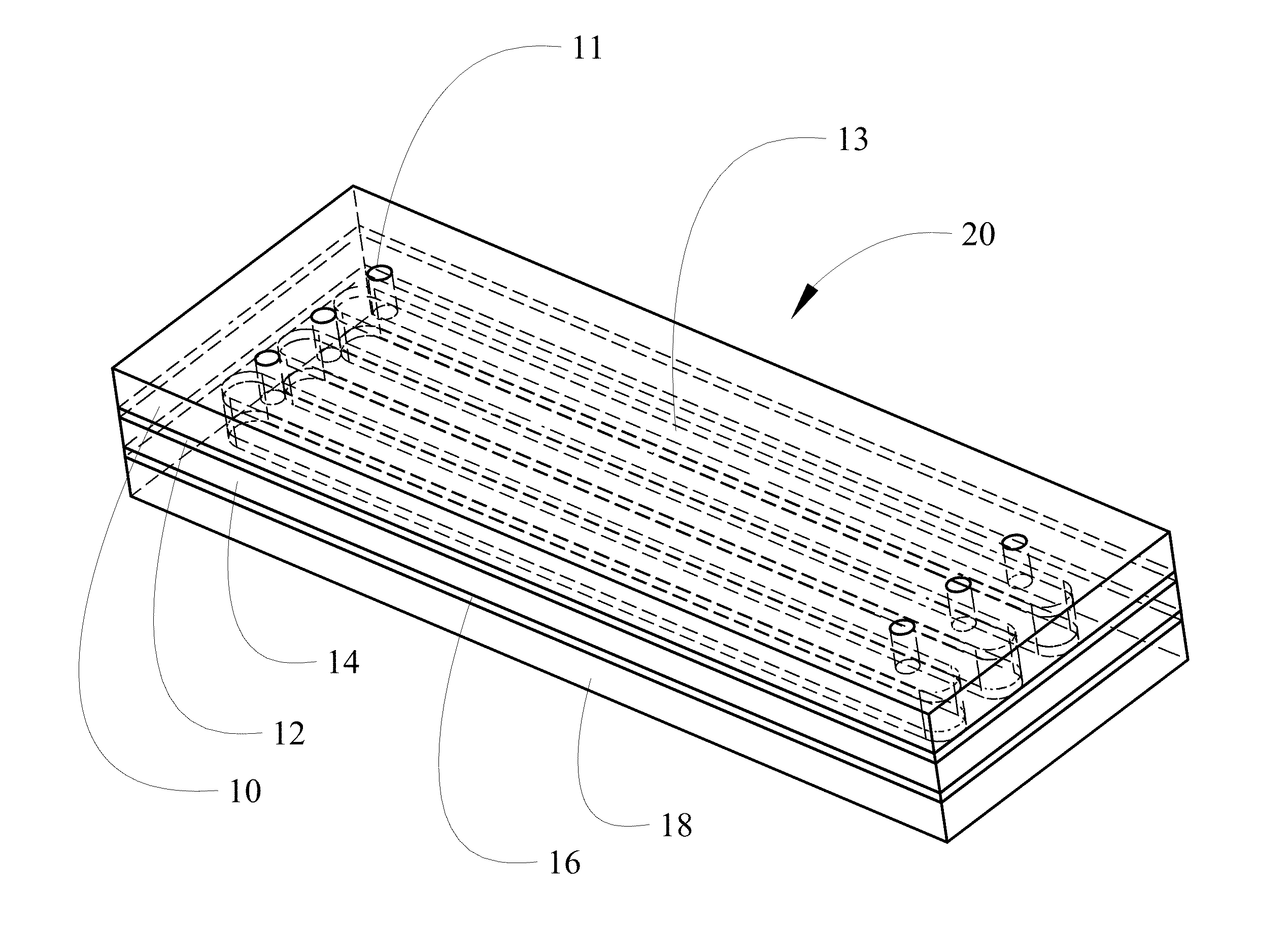
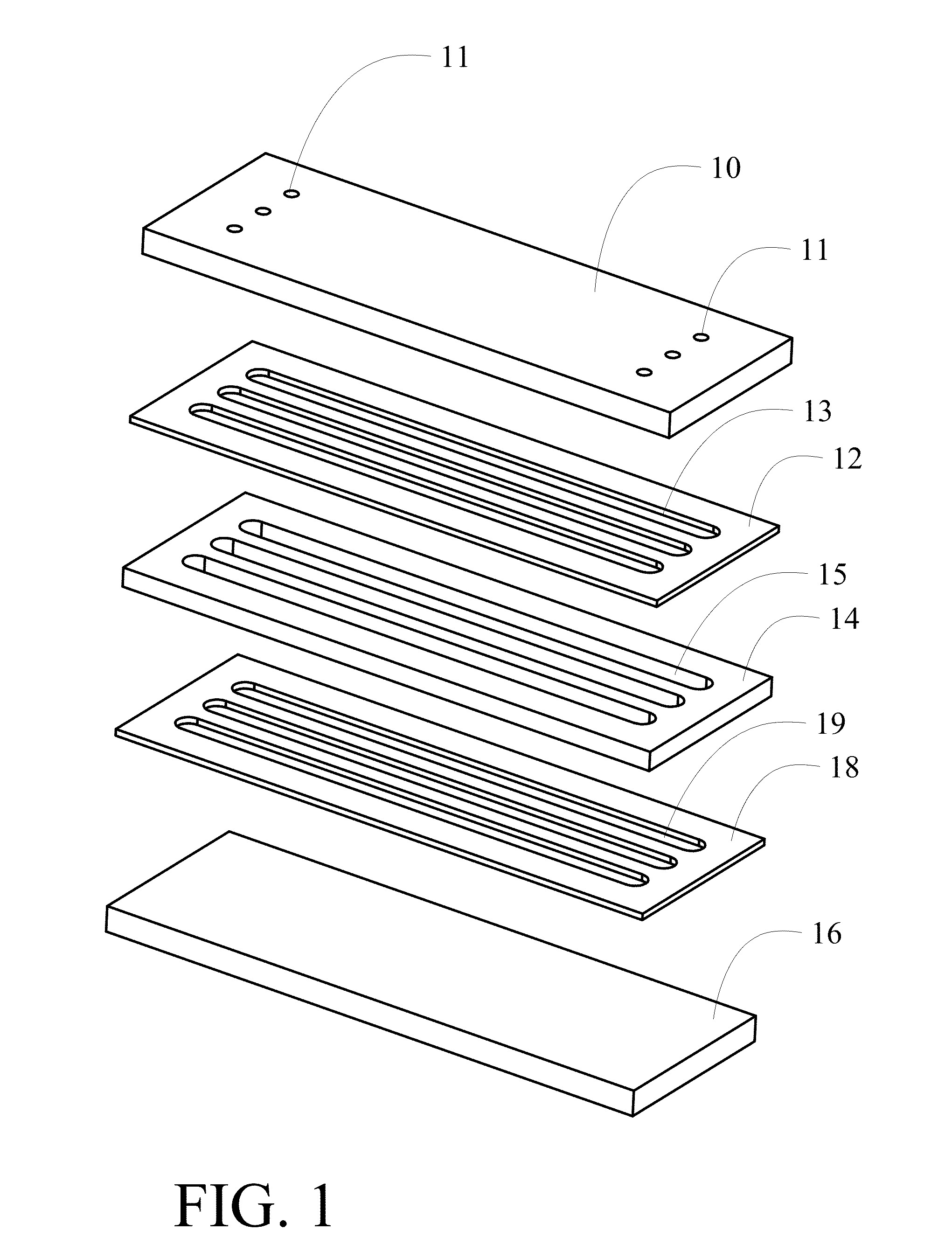
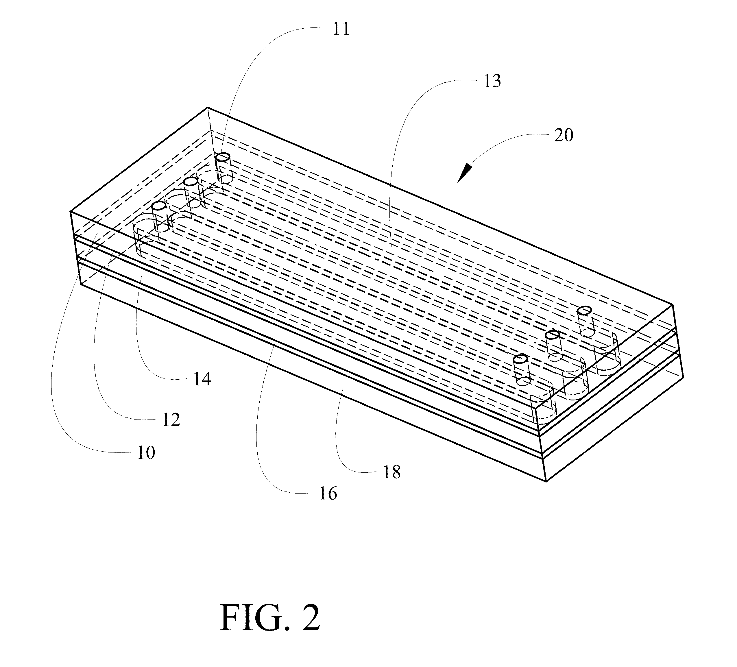
[0028]Referring to the drawings, FIG. 1 shows a first embodiment of a flow cell having a first or top substrate 10 with one or more inlet / exit holes 11. ...


PUM

PropertyMeasurementUnit
Temperatureaaaaaaaaaa
Electrical conductoraaaaaaaaaa
Adhesivityaaaaaaaaaa

Abstract

A flow cell incorporates a first substrate with a metal layer on one surface. A tape layer having flow channels is adhered to the first substrate. A second substrate having a second metal layer on one surface is adhered to the tape layer opposite the first substrate. At least one of the first and second metal layers includes mating cutouts to at least partially expose the flow channels.

Description

REFERENCE TO RELATED APPLICATIONS[0001]This application is copending with U.S. application Ser. No. 13 / 291,956 filed Nov. 8, 2011 entitled ROOM TEMPERATURE GLASS-TO-PLASTIC AND GLASS-TO-CERAMIC / SEMICONDUCTOR BONDING having a common assignee with the present application, the disclosure of which is incorporated herein by reference.BACKGROUND INFORMATION[0002]1. Field[0003]Embodiments of the disclosure relate generally to the field of taped interlayer flow cells and more particularly to a method and structure for producing a taped interlayer flow cell with precision tape geometry and cell assembly including masking of the tape layer and conductive trace formation.[0004]2. Background[0005]Microfluidic devices, often referred to as flow cells, provide very precise means to carry out complicated biochemical reactions to acquire important chemical and biological information. Among other advantages, microfluidic systems reduce the required number of samples and quantities of reagents employ...

Claims


Application Information

Patent Timeline
IPC IPC(8): B01L3/00C23F1/00
CPCB01L3/502707B01L2300/0887B01L2200/12C23F1/00B01L2300/0645B01L2400/0415B32B3/04B32B3/263B32B3/266B32B7/06B32B7/12B32B9/005B32B9/041B32B9/045B32B15/08B32B15/18B32B15/20B32B27/06B32B27/08B32B27/281B32B27/285B32B27/304B32B27/36B32B27/40B32B2255/00B32B2255/10B32B2255/205B32B2307/412B32B2307/546B32B2307/58B32B2307/748
Inventor KARAM, RAYMOND, M.ROUSSOS, GEORGESCHOBOT, ANTHONY, T.
Owner CORNING INC
Why Eureka
Eureka Blog
Learn More