
Fork-Lift Truck

a forklift and truck body technology, applied in the field of forklift trucks, to achieve the effect of avoiding damages and/or dangerous situations, improving operator ergonomics, and improving safety

Inactive Publication Date: 2016-03-31
BT PROD
View PDF25 Cites 103 Cited by
  • Summary
  • Abstract
  • Description
  • Claims
  • Application Information

AI Technical Summary

Benefits of technology

This patent describes a method for improving a fork-lift truck by adding an optical detector and analysing unit. The optical detector can be placed on the fork-lift truck and used to detect the position of an object placed on top of it. This technology allows for precise positioning of the object without the need for additional markings, and even if the optical detector is moved a little bit, the system can still accurately locate the object. This technology can be easily added to existing fork-lift trucks, making it a convenient and affordable improvement.

Problems solved by technology

However the prior art does not discuss how to avoid bad position control.

Method used


Image

  • Fork-Lift Truck
  • Fork-Lift Truck
  • Fork-Lift Truck

Examples


embodiment 1

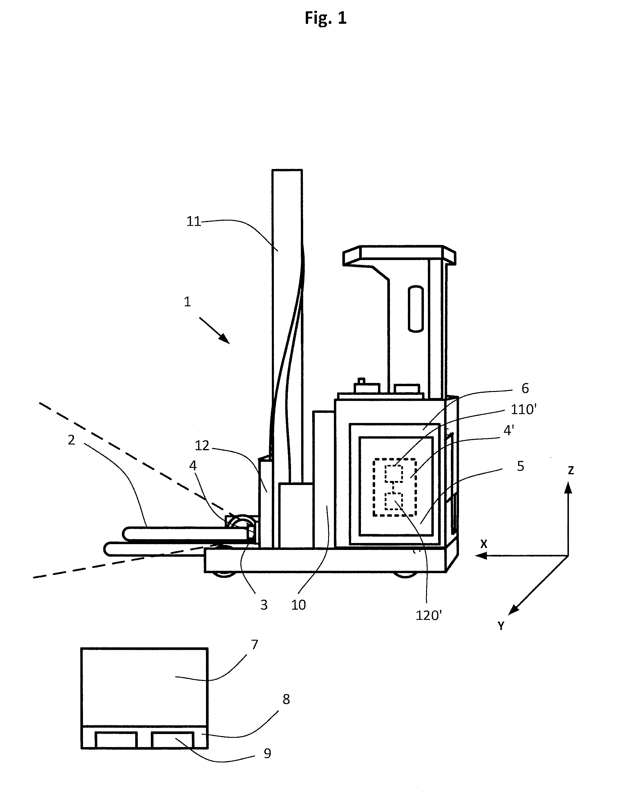
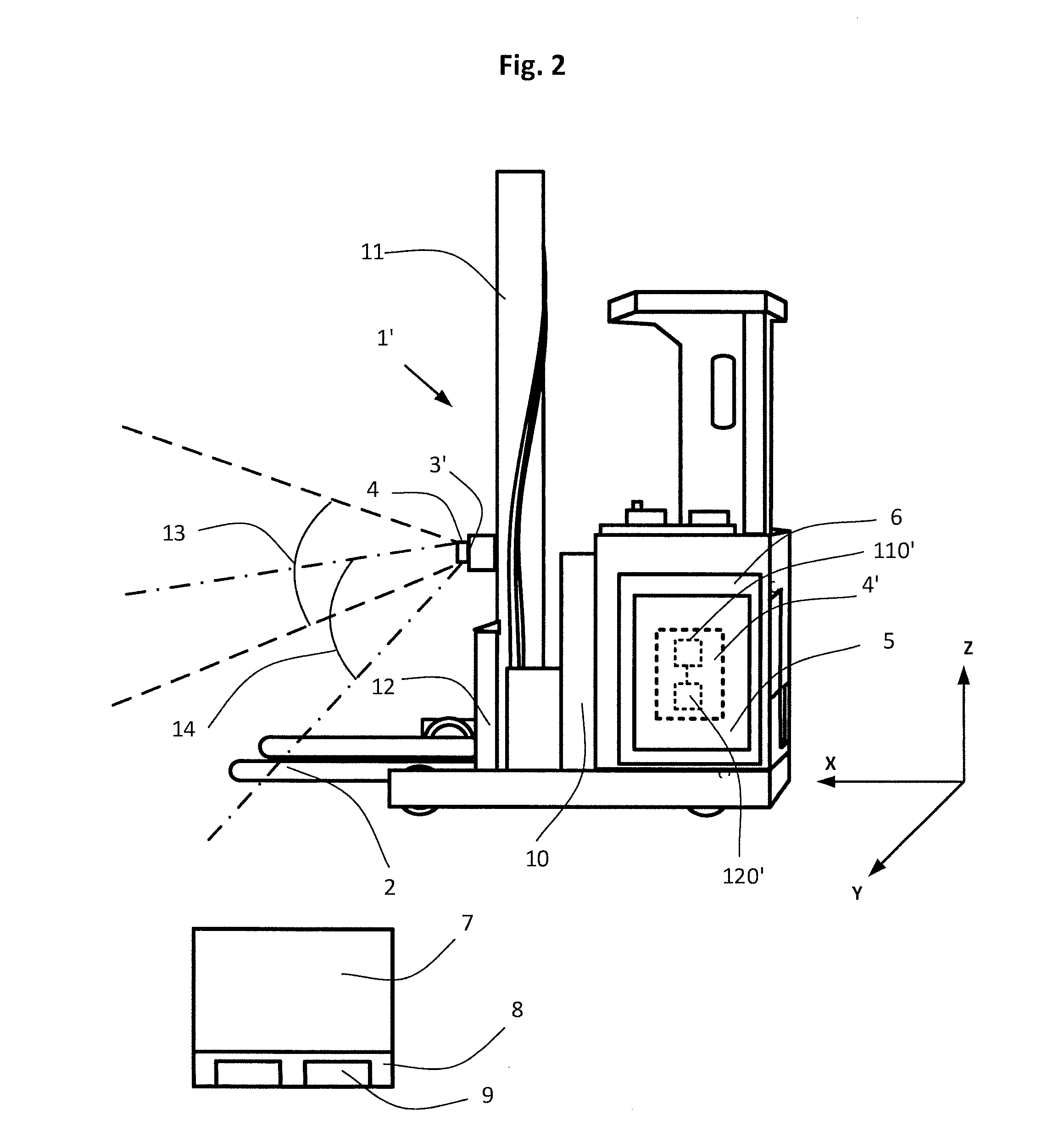
[0056]In order to also be able to perform the tasks already mentioned in relation with embodiment 1, the optical detector 3′ is movable between at least two positions and / or orientations, or has an extended field of view. The mobility is preferably added by a motorised device that supports the optical detector 3′. This motorised device is preferably controlled by the optical analysing unit 4, 4′. Thus, when in position 14 the optical detector 3′ acts as described in relation to FIG. 1. Especially the detector 3′ in combination with the analysing unit 4, 4′ will be able to identify the load carrier 2.

[0057]It should be understood that the effect of having the first position 14 and the second position 13 can, alternatively, be achieved by an optical detector 3′ that has a field of view that allows to detect both over a load 7, if loaded, and also to detect the load carrier 2, if unloaded, without altering the position and / or orientation of the optical detector 3′. When referring to th...

second embodiment

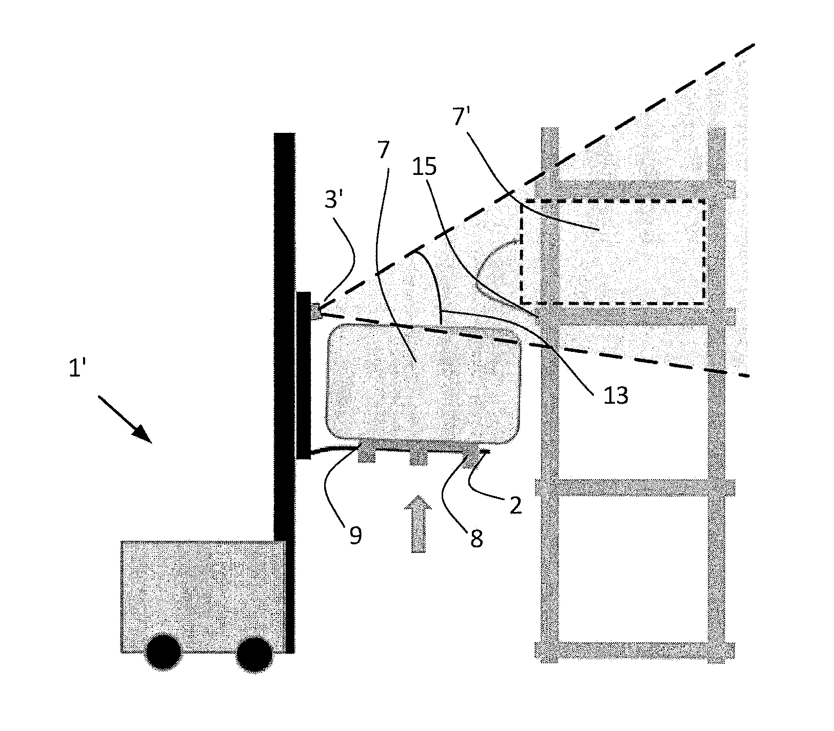
[0061]A fork-lift truck 1′ has picked up a load according to the procedure described with the second embodiment, where the optical detector 3′ has been in position 14. The fork-lift truck 1′ has now approached a racking, see FIG. 4. The fork-lift truck 1′ has found its position, for example by a general navigation system. The optical detector 3′ assumes position 13, such that it can detect over the load 7, as can be viewed from FIG. 4. As the load carrier 2 lifts the load 7 up, the optical detector 3′ detects any protruding feature of the rack. Protruding features can for example be a cargo 7′ or a part of the racking 15. The optical analysing unit 4, together with the load carrier unit 5 takes measures in order to prevent a collision. These measures can be, stop the lifting process, alter the position of the load by controlling the drive motor of the fork-lift truck 1′, or, if it is determined that the protrusions are so far extending that it is not possible to pass, the lifting pr...


PUM

PropertyMeasurementUnit
Volumeaaaaaaaaaa
Heightaaaaaaaaaa

Abstract

A fork-lift truck 1, 1′ including a load carrier 2, an optical detector 3, 3′ having a first field of view and arranged to provide an output, wherein the optical detector 3, 3′ is movable together with the load carrier 2, an optical analysing unit 4, 4′ arranged to analyse the output from said optical detector 3, 3′. The optical analysing unit 4, 4′ is arranged to analyse the output from the optical detector 3, 3′ so as to identify a first three-dimensional object, said first three-dimensional object being the load carrier 2, and a second three-dimensional object based on the output from the optical detector 3, 3′, and to determine the three-dimensional position of the identified load carrier 2 relative to the identified second three-dimensional object. Further a method for operating a fork-lift truck, a method for modifying a fork-lift truck and a computer program product.

Description

CROSS-REFERENCE TO RELATED APPLICATIONS[0001]The present application claims the benefit of European Patent Application No. 14186471.0 filed Sep. 25, 2014, which is fully incorporated herein by reference.STATEMENT REGARDING FEDERALLY SPONSORED RESEARCH OR DEVELOPMENT[0002]Not applicable.FIELD OF THE INVENTION[0003]The present invention relates to a fork-lift truck, a method of operating a fork-lift truck, a method of modifying a fork lift truck, and a computer program product.BACKGROUND OF THE INVENTION[0004]From US 2004 / 0073359 it is known to use a camera for picking up an image of a cargo handling target and acquire an image data of a mark affixed to the cargo handling target. The discussed fork-lift of this document uses cargo handling targets for position control.SUMMARY OF THE INVENTION[0005]The prior art discusses the usage of cargo handling targets in order to achieve positioning when approaching a cargo. However the prior art does not discuss how to avoid bad position control...

Claims


Application Information

Patent Timeline
IPC IPC(8): B66F9/075B66F9/14G06T7/00H04N13/02
CPCB66F9/0755H04N13/0203G06T2200/04B66F9/14G06T7/0042G05D1/0253B66F9/24G06T7/73H04N13/204
Inventor SVENSSON, RUNEPERSSON, MAGNUSFRID, HAKAN
Owner BT PROD
Features
  • Generate Ideas
  • Intellectual Property
  • Life Sciences
  • Materials
  • Tech Scout
  • Unparalleled Data Quality
  • Higher Quality Content
  • 60% Fewer Hallucinations
Learn More