UV irradiation apparatus with an additional monochromatic radiation source

a radiation source and irradiation apparatus technology, applied in the direction of nuclear engineering, transportation and packaging, railway signalling, etc., can solve the problems of recurring problems, damage to the substrate to be irradiated, resistance to micro-scratching, etc., and achieve good resistance to micro-scratching and increase brittleness

Inactive Publication Date: 2016-03-31
OERLIKON SURFACE SOLUTIONS AG PFAFFIKON
View PDF6 Cites 0 Cited by
  • Summary
  • Abstract
  • Description
  • Claims
  • Application Information

AI Technical Summary

Benefits of technology

The present invention is concerned with providing a paint with good resistance against micro-scratching without increasing its brittleness. The invention also provides a method for manufacturing a paint layer that has good resistance against micro-scratching without being too rigid. This is achieved by using a polychromatic mercury-vapor lamp and a short-wave UV-C lamp to cross-link the bulk and surface of the paint, resulting in higher surface hardnesses without compromising the overall flexibility of the paint.

Problems solved by technology

The high percentage of IR radiation leads to high processing temperatures which can damage the substrates to be irradiated.
Particularly in the field of the automotive industry, resistance to micro-scratching, for example in the context of the resistance against car wash facilities, is a recurring issue.
A drawback of this is, however, that the increased cross-linking of the paint layers leads to an increased brittleness caused by, among other things, increased shrinking during polymerization.
If, for example, the temperature changes or mechanical stresses occur, when the underlying material changes its extension corresponding to a different coefficient of thermal expansion, the above-mentioned increased brittleness with stronger cross-linking, has the effect that the paint no longer adheres on the material and thus flakes.
In particular also in the context of stone chipping, such a brittle paint can additionally lead to fatal flaking of the paint.

Method used


Image

  • UV irradiation apparatus with an additional monochromatic radiation source
  • UV irradiation apparatus with an additional monochromatic radiation source

Examples


Embodiment Construction

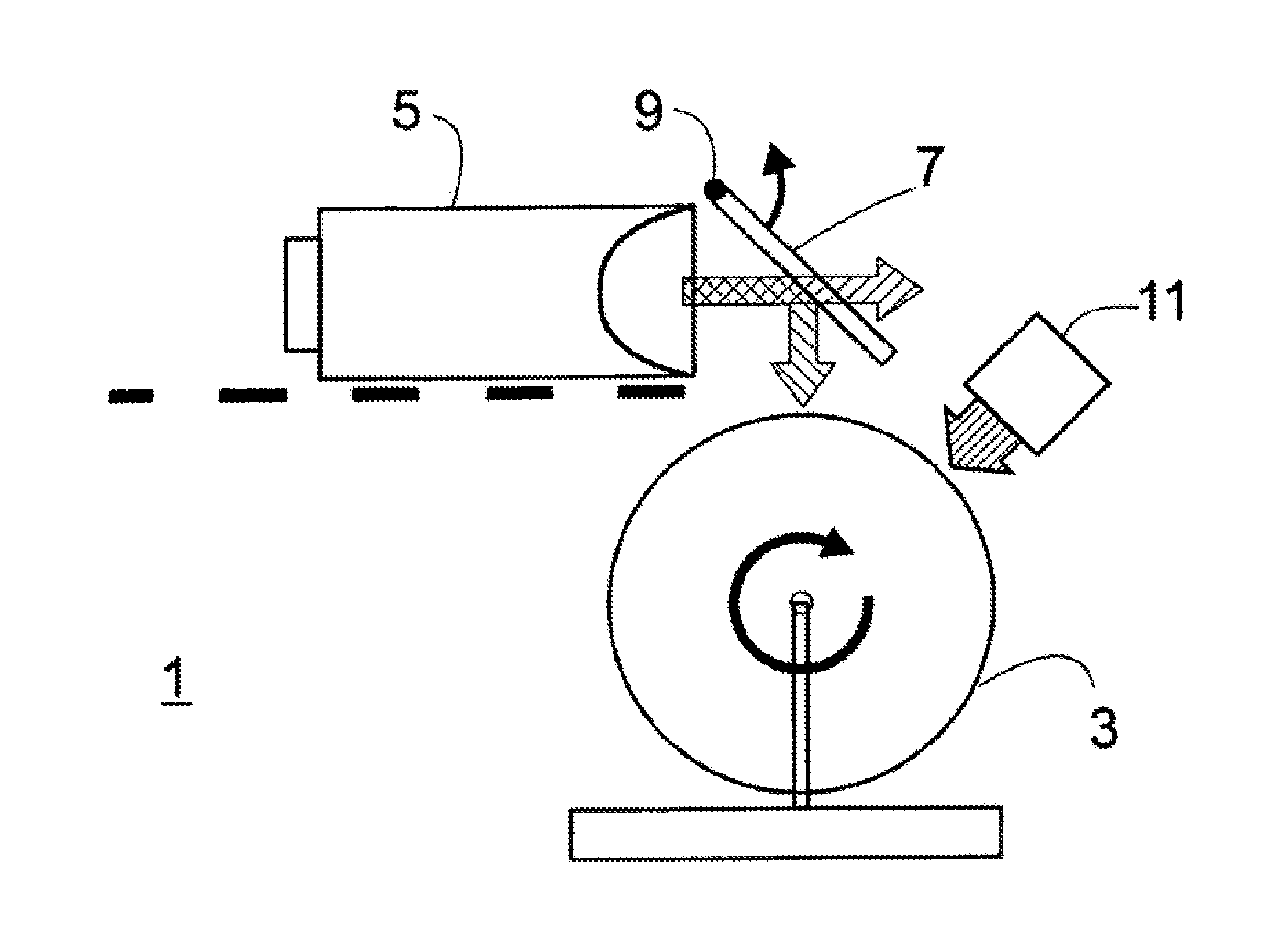
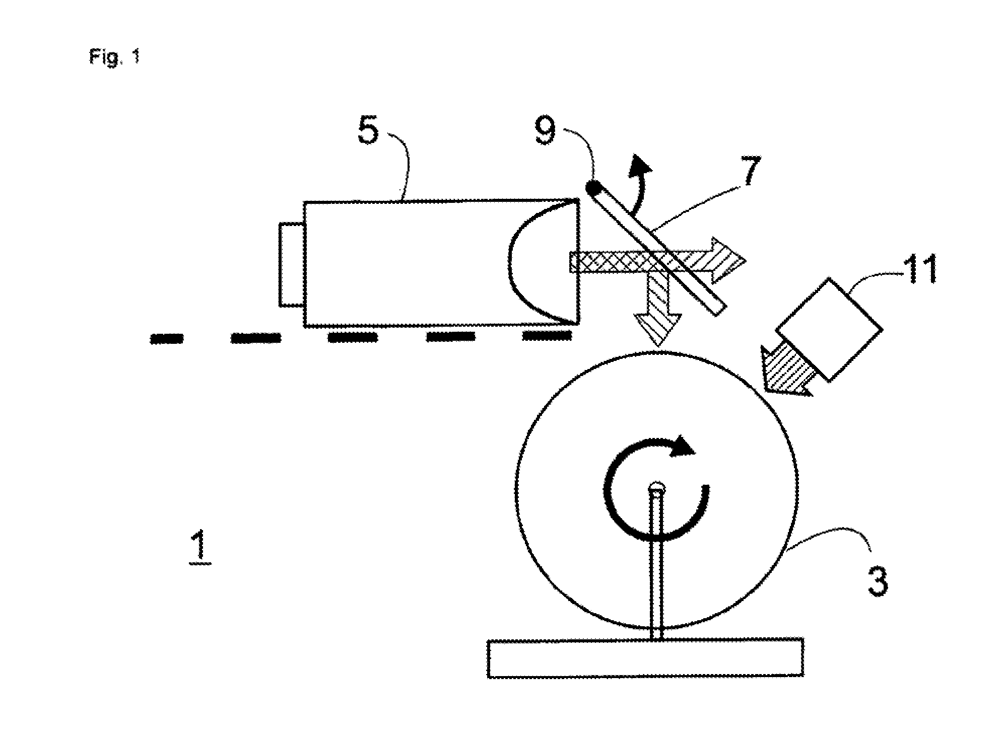
[0016]FIG. 1 shows an apparatus 1 for cross-linking of substrates coated with UV paint, arranged on a spindle 3. As indicated by the arrow, the spindle slowly rotates in the clockwise direction. Above the spindle, a high-pressure mercury-vapor lamp 5 is arranged, emitting a wide spectrum of radiation, comprising UV, visible and IR radiation, indicated by the arrow end provided with crosshatching.

[0017]This radiation impinges on a cold, light mirror 7 rotated at an angle of 45° with respect to the main radiation direction. The cold light mirror 7 essentially reflects the UV light downwards towards the spindle and essentially transmits visible light, and IR radiation.

[0018]UV light from the high-pressure mercury-vapor lamp 5 impinging on the surface of the painted substrates arranged on the spindle, is absorbed by the paint layer and leads to the polymers in the paint essentially uniformly cross-linking to a certain degree. In the present example, the substrates are exposed to the UV ...


PUM

PropertyMeasurementUnit
temperaturesaaaaaaaaaa
angleaaaaaaaaaa
wavelengthaaaaaaaaaa

Abstract

A component, the surface of which is at least partially covered with a coating, wherein the coating comprises a PVD coating arranged between a first paint layer and a second paint layer and the first paint layer forms a base coat layer on the surface and the second paint layer forms a top coat layer having a top coat thickness on the PVD coating, wherein at least the top coat layer was produced with UV-curable paint. Proceeding from the interface of the PVD coating in a region smaller than the top coat thickness, the top coat layer has a lower degree of cross-linking induced by UV light than in the part of the top coat layer connected to said region. The invention relates in particular to a method for producing such a component.

Description

FIELD OF THE INVENTION[0001]The present invention relates to a method for UV cross-linking of paint layers. The invention also relates to an irradiation apparatus for carrying out the method.BACKGROUND OF THE INVENTION[0002]Paints applied to substrates are cured and dried by means of UV cross-linking. The paint remains fluid until it is cross-linked and can be abruptly hardened after application on a substrate.[0003]As the UV radiation source, in most cases, a radiation source is used which emits both UV radiation and visible light and a high percentage of infrared radiation (IR radiation). The high percentage of IR radiation leads to high processing temperatures which can damage the substrates to be irradiated. A mercury-vapor lamp can be mentioned as an example of such a radiation source. In particular if the painted substrates are plastic substrates, critical temperatures are often reached if the conventional irradiation is used. For the plastic material known as ABS, for example...

Claims


Application Information

Patent Timeline
Patent Type & Authority Applications(United States)
IPC IPC(8): C23C14/58
CPCC23C14/58B05D3/067B05D7/02B05D7/53B05D7/57B05D3/0209B05D2490/50B05D3/06
Inventor SCHAEFER, RUEDIGIERKASPAR, MARTIN
Owner OERLIKON SURFACE SOLUTIONS AG PFAFFIKON
Why Eureka
Try Eureka