Pre-distancing collapsible system particularly for the elements of a structural frame

a technology of structural frame and dislocation system, which is applied in the direction of buildings, walls, buildings, etc., can solve the problems of not being very cost-effective and therefore less used, requiring extensive labor in the factory, and requiring additional time, etc., to achieve simple and quick installation and high precision

Active Publication Date: 2016-03-31
PRE FRAMING
View PDF13 Cites 0 Cited by
  • Summary
  • Abstract
  • Description
  • Claims
  • Application Information

AI Technical Summary

Benefits of technology

[0013]Purpose of the present invention is to provide a prefabrication system that allows the production of inexpensive, high precision, structural frames made out of wood, metal or other materials, a simple and quick installation on site, eliminating completely the manual measuring, marking & cutting operations usually necessary on-site and the need to use a crane for the installation.

Problems solved by technology

This phase requires the presence on site of highly qualified personnel, it is the most complex and it is subject to errors caused by incorrect interpretation of the drawings or by human error in the marking process or cutting of the components.
Moreover, after having correctly positioned the various components to the ground, components as studs typically are repositioned elsewhere for cutting and then placed back in position, an operation which requires additional time.
In those cases these system is competitive compared to the traditional platform framing on-site construction but usually they are not very cost-effective and therefore less used.
For the prefabrication of entire walls and ceiling usually the money saved thanks to the use of better systems within the factory and thanks to a faster installation on-site is often compensated by the fixed costs of the facility where the walls are manufactured, the cost of the equipment used, which is not fully automated, therefore it still requires extensive use of labor in the factory, and transportation costs, much higher than the simple transportation of the lumber needed for traditional on-site construction (which take up only about 25% of prefabricated walls and floors volume during transportation).
Furthermore there is the cost of temporary indoor storage space for finished walls and sometimes the crane cost for the installation on-site.
In addition most of the times contractors does not own the factory, for the manufacturing of walls and floors, and the crane needed for the installation on-site, so they need to pay third-party suppliers, reducing their profit.
About kit-houses, with all the elements pre-cut in an off-site facility, the transportation cost is not substantially different, but the costs are increased by the need to cut, number, mark and make a schedule of all the components, one by one, and by the fact that on the construction site somebody need to interpret the drawings and the schedule of all the singular components and then find them.
This can be quite complex and time consuming, making this system usually not competitive compared to the traditional on-site marking & cutting of the components, especially for the construction of a single home.
Probably the drawback of this systems can be the high production cost, due to a higher number of industrial processes required, the greater amount of material required and the transportation cost, more competitive compared to other known types but still greater than the transportation cost of the individual, not yet assembled, components.
Moreover, often this systems work only for light gauge metal frames, still far less used than wood.

Method used


Image

  • Pre-distancing collapsible system particularly for the elements of a structural frame
  • Pre-distancing collapsible system particularly for the elements of a structural frame
  • Pre-distancing collapsible system particularly for the elements of a structural frame

Examples


Embodiment Construction

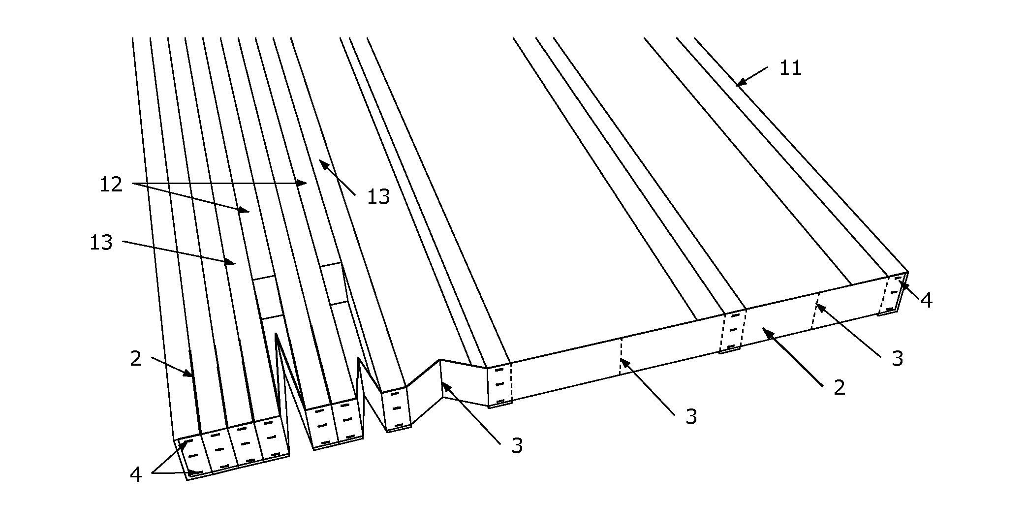
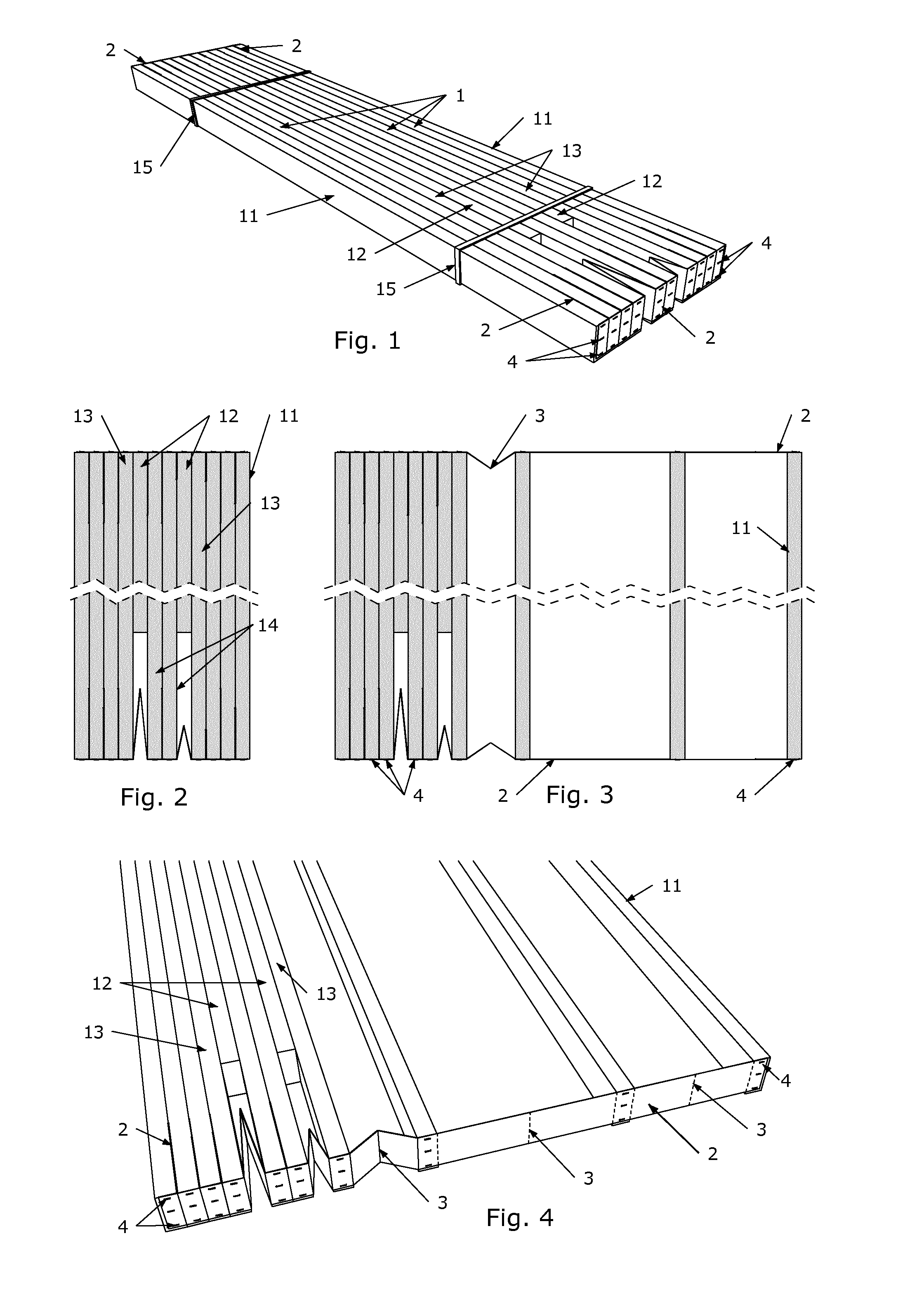
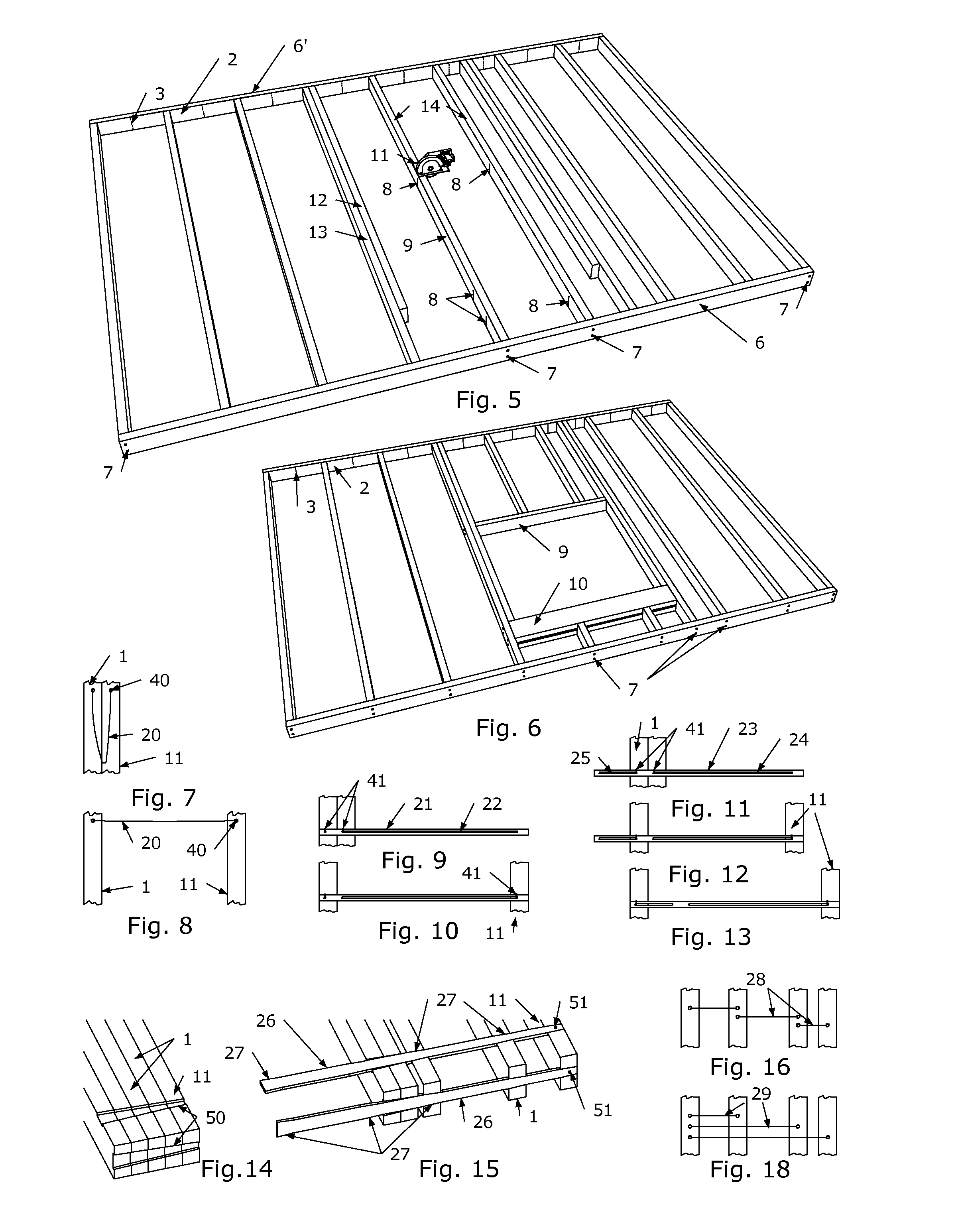
[0037]The system, as illustrated in the drawings, comprises the structural vertical components of the wood frame 1, also called studs, of a wall with a window opening in the middle. The spacers 2 are fastened to each head of the studs by staples or nails 4. The spacers are made of foldable material (e.g. aluminum sheet 2 / 10 mm thick) and the length of the portion of foldable material between one stud and the other depends on the distance designed for the frame. The spacers are folded between a stud and the other during storage and transportation as shown in FIG. 1, where a wall is packed with strips 15, ready for transportation. The two studs 12 are shorter compared to the others, they are the so called “jack studs”, supporting the window header 10. The two jack studs 12 are fastened to the adjacent full-height studs 13, the so called “king studs”.

[0038]In FIG. 5 are also visible the partial cuts 8 in the two studs 14, and the two horizontal components of the frame 6 and 6′ (called ...


PUM


Abstract

The present invention refers to a pre-distancing collapsible system particularly for the elements of a structural frame of a building. An embodiment of the invention comprises at least three components of a structural frame and at least two spacers, not being these spacers structural elements of the frame, fastened to the heads of aforementioned components of the frame, and said spacer being foldable.

Description

FIELD OF THE INVENTION[0001]The invention relates to a prefabrication system for the structural components of a partially pre-assembled frame, in wood or other material, in particular for the construction of interior and exterior walls, floors, roof trusses and roofs of buildings.BACKGROUND[0002]The typical platform framing technique, which is also the most common light framing construction technique (in Usa, Canada, Australia, UK) requires the interpretation of blueprints, often designed using a CAD software, and the selection, measurement, marking, cut and assembly of many components, (as studs) that need to be spaced at specific distances. All the work is made on the construction site where weather may impede construction.[0003]This phase requires the presence on site of highly qualified personnel, it is the most complex and it is subject to errors caused by incorrect interpretation of the drawings or by human error in the marking process or cutting of the components. Moreover, a...

Claims


Application Information

Patent Timeline
Patent Type & Authority Applications(United States)
IPC IPC(8): E04B1/343E04B2/56
CPCE04B1/34357E04B2001/34389E04B2/56E04C2/386E04B1/3441E04B2/707E04B1/34317E04C2/38E04B1/343
Inventor SICA, MAURO
Owner PRE FRAMING
Why Eureka
Try Eureka