

Ejector
a technology of ejector and nozzle, which is applied in the direction of machines/engines, subcoolers, lighting and heating apparatus, etc., can solve the problems the boiling delay of partial liquid-phase refrigerant, and the inability to improve the efficiency of the nozzle to a desired value, so as to achieve the effect of reducing the efficiency of the nozzle of the ejector
- Summary
- Abstract
- Description
- Claims
- Application Information
AI Technical Summary
Benefits of technology
Problems solved by technology
Method used
Image

Examples
first embodiment
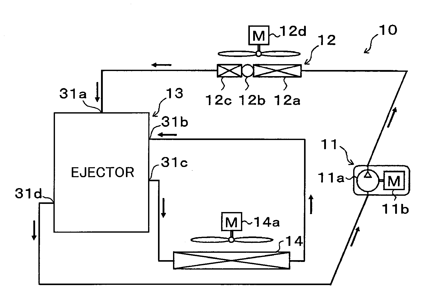
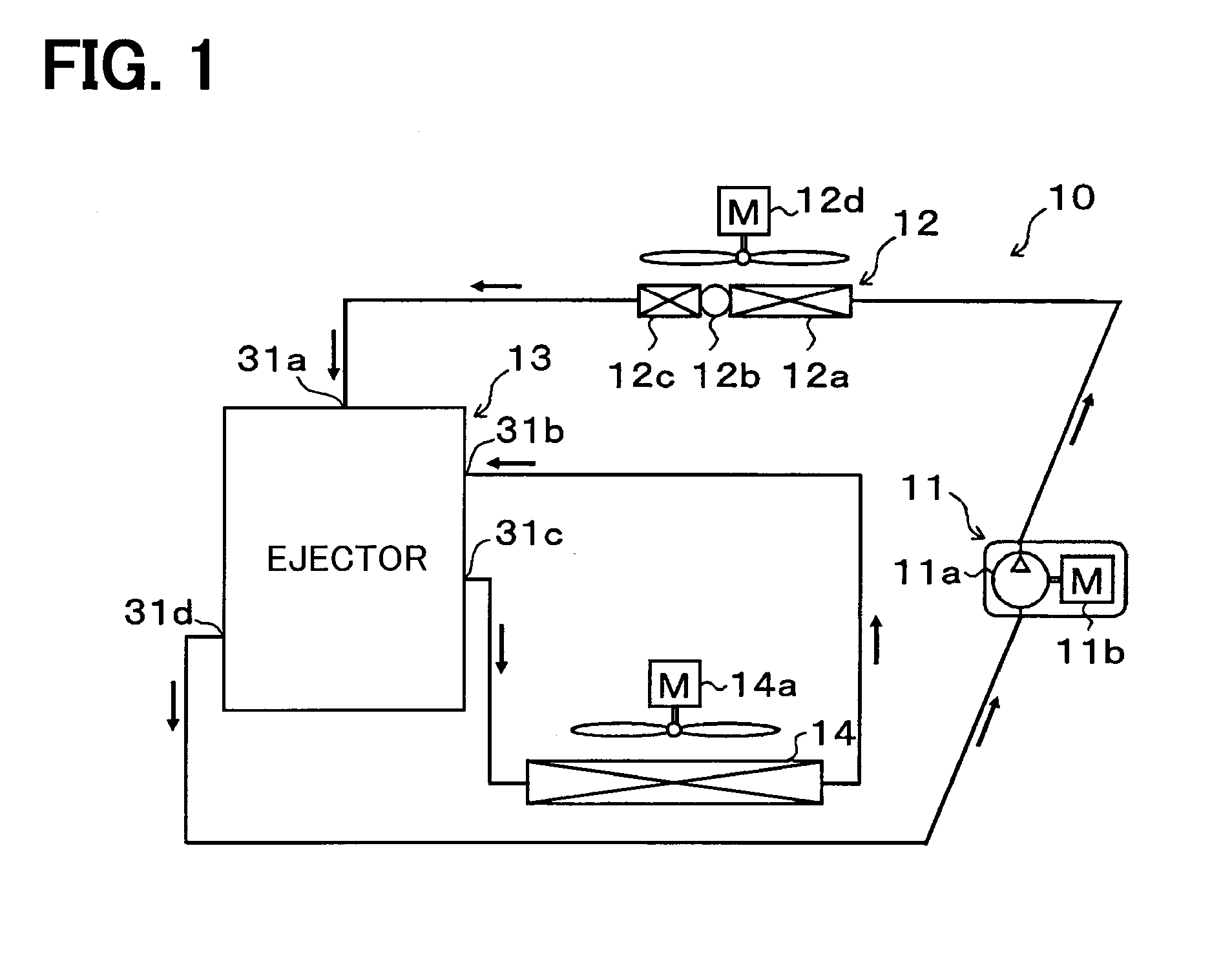
[0040]A first embodiment of the present disclosure will be described with reference to FIGS. 1 to 5. As illustrated in an overall configuration diagram of FIG. 1, an ejector 13 according to this embodiment is applied to a refrigeration cycle device having an ejector as a refrigerant depressurizing device, that is, an ejector refrigeration cycle 10. Moreover, the ejector refrigeration cycle 10 is applied to a vehicle air conditioning apparatus, and performs a function of cooling a blast air which is blown into a vehicle interior that is a space to be air-conditioned.
[0041]In addition, an HFC-based refrigerant (more specifically, R134a) is applied as the refrigerant in the ejector refrigeration cycle 10, and a vapor compression type subcritical refrigeration cycle in which high pressure-side refrigerant pressure does not exceed critical pressure of the refrigerant is configured. It is needless to say that an HFO-based refrigerant (for example, R1234yf) may be employed as the refrigera...
second embodiment
[0126]In the first embodiment, the example in which the swirling flow of the refrigerant is generated in the interior of the upstream swirling space 301 is described. In this embodiment, a description will be given of an example in which, as illustrated in FIGS. 6 to 8, with the application of a swirling promotion member 39, a swirling flow of the refrigerant is generated in the outer peripheral side of the upstream swirling space 301, and the refrigerant having a velocity component in the swirling direction flows into the upstream swirling space 301. FIGS. 6 to 8 correspond to FIGS. 2 to 4 in the first embodiment, respectively, and the same or equivalent parts to those in the first embodiment are denoted by identical symbols.
[0127]Specifically, a swirling promotion member 39 according to this embodiment includes a plate 39a formed into a disc shape, multiple flow regulating plates 39b projected downward from an outer peripheral part of the plate 39a, and a cylindrical protruding po...
third embodiment
[0139]In the ejector refrigeration cycle 10a of this embodiment, as illustrated in an overall configuration diagram of FIG. 9, the ejector 13 according to the first embodiment is replaced with an ejector 53 and a gas-liquid separator 60.
[0140]The ejector 53 according to this embodiment does not have a function of the gas-liquid separator, but as in the ejector 13 of the first embodiment, performs a function of a refrigerant depressurizing device and also performs a function of a refrigerant circulation device (refrigerant transport device). A specific configuration of the ejector 53 will be described with reference to FIG. 10.
[0141]The ejector 53 has a nozzle 531 and a body 532 as illustrated in FIG. 10. First, the nozzle 531 is made of metal (for example, stainless alloy) shaped into substantially a hollow cylinder gradually tapered toward a flowing direction of the refrigerant, and the refrigerant flowing into the nozzle 531 is isentropically depressurized, and ejected from a refr...
PUM
 Abstract
Description
Claims
Application Information