

Magnetic Refrigeration System with Improved Coaxial Valve
a technology of coaxial valve and magnetic refrigeration system, which is applied in the direction of refrigeration machines, machines using electric/magnetic effects, lighting and heating apparatus, etc. it can solve the problems of under-utilization of magnetocaloric beds and reduce efficiency, so as to facilitate balancing and reduce the influence of wear on leakag
- Summary
- Abstract
- Description
- Claims
- Application Information
AI Technical Summary
Benefits of technology
Problems solved by technology
Method used
Image

Examples
first embodiment
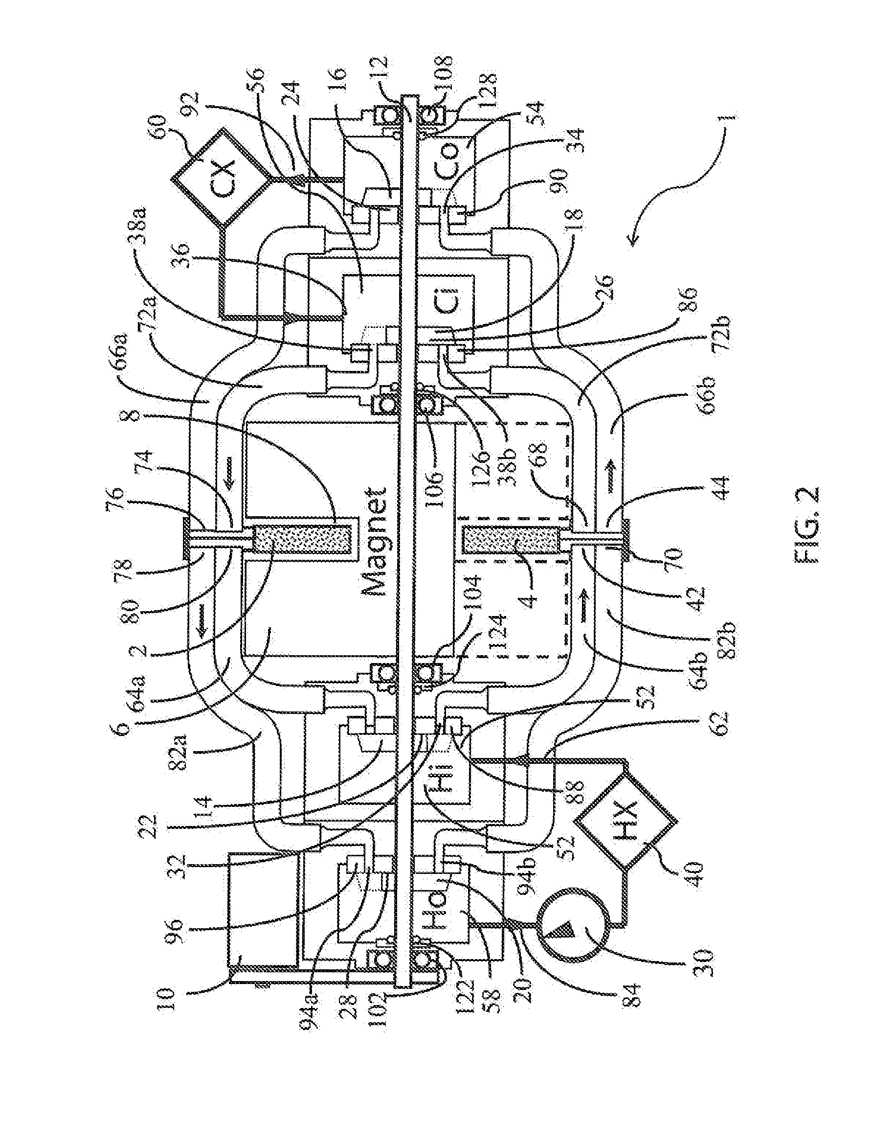
[0073]The invention comprises a “rotating magnet” magnetic refrigerator (RMMR) which uses rotary disk valves to control flow to and from the beds where these valves are located coaxially with the shaft rotating the magnet assembly, and where a compression mechanism on the valve disks is adjustable after assembly of the valves, and maintains sealing as the disks wear. An overview of the arrangement of components of this invention is shown in FIG. 2. FIG. 2 shows a cross section of a two-bed system 1, where a first bed 2 (magnetized) is within the gap 8 of the magnet assembly 6 while a second bed 4 (demagnetized) is outside the gap 8 of the assembly. A motor 10 (which may be an electric motor) rotates the central shaft 12, which is mounted to bearings 102, 104, 106 and 108, and passes through rotary seals 122, 124, 126 and 128. This central shaft 12 also drives the rotors 14, 16, 18, 20 in each of the coaxial valves 22, 24, 26, 28. A pump 30 drives fluid flow through the system 1.
[007...
second embodiment
[0082]The improvements to the valves of this invention are shown in the detailed view of the hot side valves in FIG. 6. Both the hot inlet valve 22 and hot outlet valve 28 are of similar construction. The hot outlet valve 28 contains a stator 96 that is fixed in position and sealed against the valve housing 210. Each port in the stator is mated with a stub-tube 205 protruding from the floor of the valve housing. Each stub tube has an o-ring seal 204 to the stator. The hot outlet valve also contains a rotor 20 that rotates with the magnet 6 about the axis of the shaft 12. The rotor 20 is centered by an o-ring 228 between its ID and an inner rotating assembly 201, and is mounted to a rigid valve cup 212. The drive shaft 12 passes coaxially through the inner assembly 201 that is connected to the rotor 20 and the compression assembly 230. The compression assembly 230 is comprised of a threaded nut 218 that supports springs 220 that apply compression force against the rigid cup 212 and r...
embodiment 2
[0088]An example of another embodiment using one-way valves is shown in FIG. 8, where the cold side valves 24, 26 of embodiment 2 in FIG. 4 have been replaced by check valves 120, 121, 125, and 127 in FIG. 8.
[0089]FIG. 9 shows details on how the connection might be made between one end of a bed and the inlet and outlet pipes coming from a valve. The cold inlet pipe 72b and cold outlet pipe 66b come in from the top of the figure and enter a bed plenum assembly 110. The cold inlet pipe 72b terminates at a cold inlet port 68 and the cold outlet pipe 66b terminates in a cold outlet port 44 that connect at a rectangular opening 112 that can be attached to one side of a bed, such as the bed 4 of FIG. 2. The bed is not shown in FIG. 9.
[0090]Although two-bed embodiments are shown in FIGS. 2 through 8, it is usually advantageous to fit additional beds in the path swept by the magnet gap. The additional beds increase the cooling power and can make more efficient use of the magnet assembly. Th...
PUM
 Abstract
Description
Claims
Application Information