Spectroscopic analysis apparatus and method of calibrating spectroscopic analysis apparatus

a technology of spectroscopic analysis and analysis apparatus, which is applied in the direction of spectrometry/spectrophotometry/monochromators, instruments, optical radiation measurement, etc., can solve the problems of troublesome calibration processing, difficult detection of feature points corresponding to intrinsic wavelengths, complicated apparatus structure, etc., and achieves the effect of easy wavelength calibration

Active Publication Date: 2016-03-31
SEIKO EPSON CORP
View PDF3 Cites 29 Cited by
  • Summary
  • Abstract
  • Description
  • Claims
  • Application Information

AI Technical Summary

Benefits of technology

[0022]According to this application example, the feature point corresponding to the intrinsic wavelength of the known component in the optical spectrum is specified, and the wavelength of the optical spectrum is co

Problems solved by technology

However, when the wavelength calibration filter is provided in the apparatus in JP-A-10-153544, there is a disadvantage in that the constitution of the apparatus becomes complicated.
Moreover, when the wavelength calibration plate is used, there is a need to set the wavelength calibration plate as an imaging target during measurement, leading to an

Method used


Image

  • Spectroscopic analysis apparatus and method of calibrating spectroscopic analysis apparatus
  • Spectroscopic analysis apparatus and method of calibrating spectroscopic analysis apparatus
  • Spectroscopic analysis apparatus and method of calibrating spectroscopic analysis apparatus

Examples


first embodiment

Operational Effect of First Embodiment

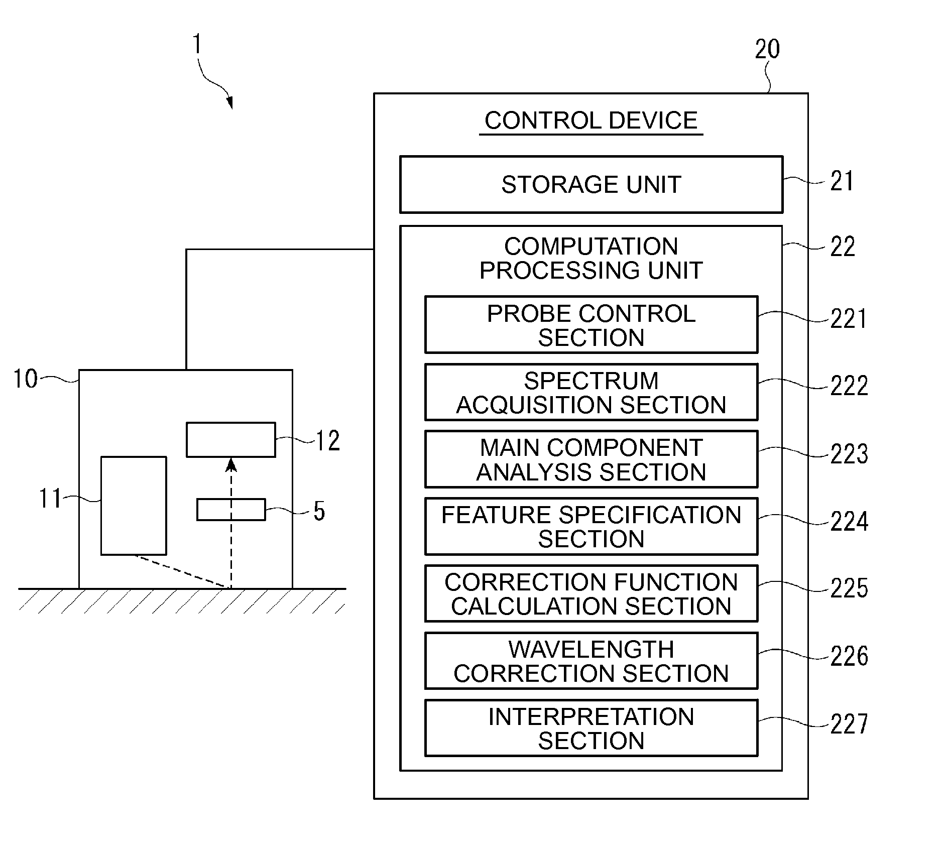
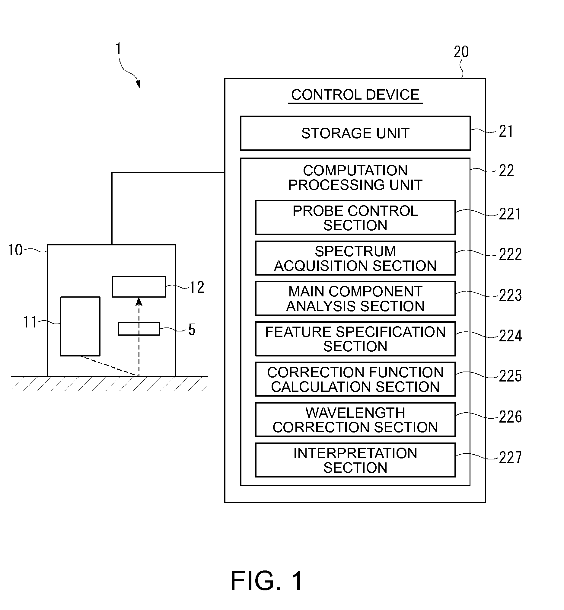
[0079]In the biological examination apparatus 1 of the embodiment, the intrinsic wavelengths (the absorption wavelengths) in the components included in the measurement target is stored in the storage unit 21 as the reference data, and the feature specification section 224 specifies the feature point which is the position with respect to the intrinsic wavelength, from the actually measured optical spectrum and the reference data. Then, the wavelength correction section 226 corrects the optical spectrum by correcting the specified wavelength of the feature point to be the intrinsic wavelength.

[0080]Accordingly, without separately using a standard calibration plate such as a white plate, the measured optical spectra can be suitably and easily corrected in a simple constitution.

[0081]In the biological examination apparatus 1 of the embodiment, the correction function calculation section 225 calculates the correction functions representing the relati...

second embodiment

[0085]Subsequently, a second embodiment according to the invention will be described.

[0086]The first embodiment describes the example in which the feature specification section 224 specifies the feature point based on the interval of the intrinsic wavelengths in a specific component. In contrast, the present embodiment is different from the first embodiment in a point of specifying the feature point based on spectrum vectors of the optical spectra.

[0087]The embodiment has a constitution similar to that of the above-described first embodiment. However, there is a difference in the reference data stored in the storage unit as well as the processing contents of the feature specification section 224. Therefore, hereinafter, descriptions will be given with reference to FIG. 1 similarly to the first embodiment.

[0088]In the embodiment, the intrinsic wavelengths of each component which becomes the analysis target, and the spectrum vector (the reference spectrum vector) are recorded as the r...


PUM


Abstract

A spectroscopic analysis apparatus includes a spectrum measurement unit that measures an optical spectrum of a measurement target, a storage unit that stores reference data in which an intrinsic wavelength with respect to a known component is recorded, a feature specification section that specifies a feature point corresponding to the intrinsic wavelength in the optical spectrum which is measured by using the reference data, and a wavelength correction section that corrects a wavelength of the feature point in the optical spectrum as the intrinsic wavelength.

Description

BACKGROUND[0001]1. Technical Field[0002]The present invention relates to a spectroscopic analysis apparatus and a method of calibrating a spectroscopic analysis apparatus.[0003]2. Related Art[0004]In the related art, regarding a spectroscopic analysis apparatus, there is a known apparatus which performs wavelength calibration processing when deviation of a wavelength occurs in a spectrum system due to environmental changes and the like (for example, refer to JP-A-10-153544).[0005]JP-A-10-153544 discloses an apparatus in which a wavelength calibration filter is set on an optical path so as to measure a light absorption spectrum for wavelength calibration during the wavelength calibration processing. Then, a peak wavelength of the measured absorption spectrum is detected, thereby specifying an angle of diffraction grating corresponding to the peak wavelength.[0006]Incidentally, in the related art, when performing calibration processing with the spectroscopic analysis apparatus, standa...

Claims


Application Information

Patent Timeline
IPC IPC(8): G01J3/28
CPCG01J3/28
Inventor SAKURAI, KAZUNORIKASAHARA, HIROKAZU
Owner SEIKO EPSON CORP
Why Eureka
Try Eureka