Optical filter device, optical module, and electronic apparatus

a filter device and optical module technology, applied in the direction of optics, instruments, mountings, etc., can solve the problems of reducing reducing the uniformity of the gap dimension, and affecting the processing accuracy of the interference filter, so as to prevent the reduction of the resolution of the interference filter of the optical filter device. , to achieve the effect of accurate processing and preventing the reduction of the interference filter

Active Publication Date: 2016-03-31
SEIKO EPSON CORP
View PDF9 Cites 7 Cited by
  • Summary
  • Abstract
  • Description
  • Claims
  • Application Information

AI Technical Summary

Benefits of technology

[0037]In the present application example, as described above, it is possible to prevent resolution of the interference filter of the optical filter device from decreasing, and to exit light from the optical filter device in a state in which the resolution is maintained. Thus, it is possible to provide an electronic apparatus which can perform accurate processing, based on light of high resolution which is emitted from the optical filter device.

Problems solved by technology

In addition, as the interference filter vibrates, distortion occurs in the substrate, and uniformity of the gap dimension can decrease along to a reflective surface.
In this way, if the gap dimension is changed or the uniformity along to the surface decreases, there is a problem in which resolution of the interference filter decreases.

Method used


Image

  • Optical filter device, optical module, and electronic apparatus
  • Optical filter device, optical module, and electronic apparatus
  • Optical filter device, optical module, and electronic apparatus

Examples


first embodiment

[0054]A first embodiment according to the invention will be hereinafter described with reference to the accompanying drawing.

Configuration of Optical Filter Device

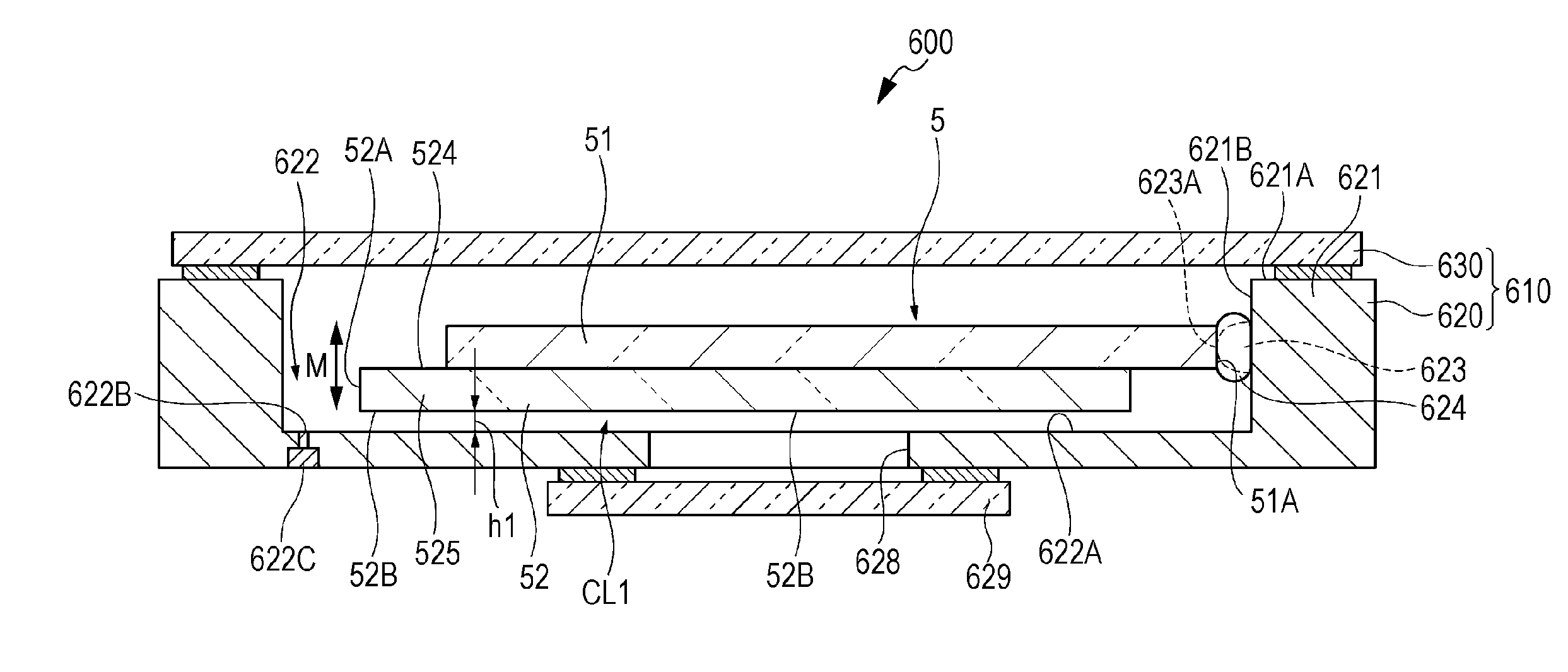
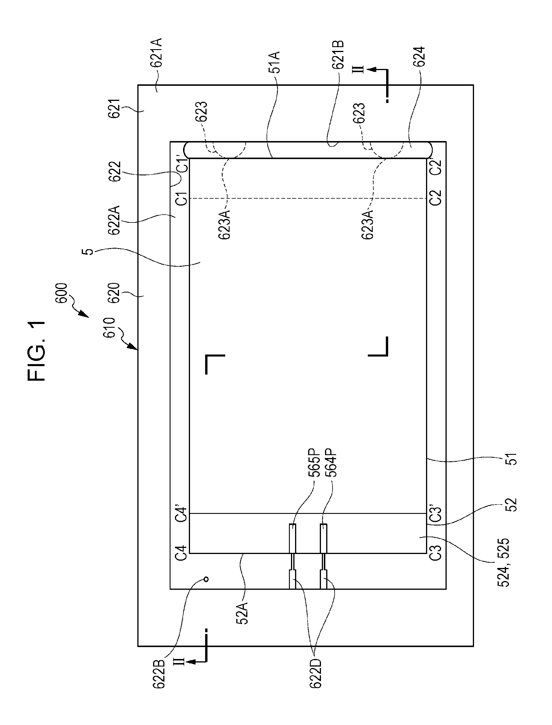
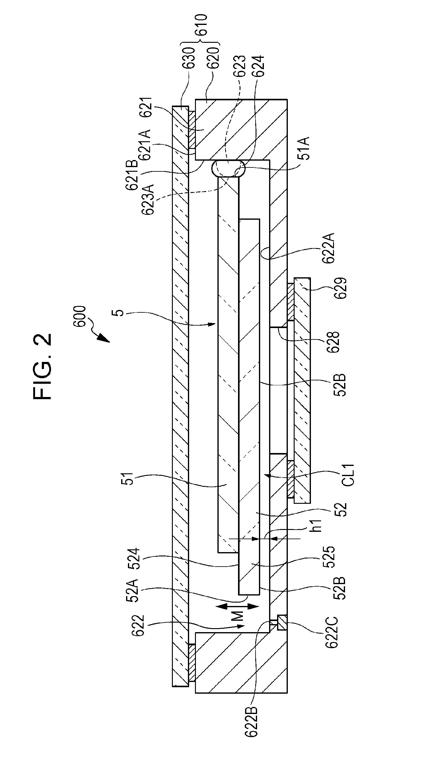
[0055]FIG. 1 is a plan view illustrating a schematic configuration of an optical filter device 600 which is a first embodiment of an optical filter device according to the invention. FIG. 2 is a sectional view taken along line II-II of FIG. 1.

[0056]The optical filter device 600 extracts light with a predetermined target wavelength from inspection target light which is incident, and exits the light. The optical filter device 600 includes a case 610, and a wavelength variable interference filter 5 that is held in the case 610. The optical filter device 600 can be incorporated into an optical module such as a color measurement sensor, or an electronic apparatus such as a color measurement device or a gas analyzing device. The configuration of the optical module and the electronic apparatus which include the optical filter dev...

second embodiment

[0153]Subsequently, a second embodiment according to the invention will be described with reference to the accompanying drawings.

[0154]In the second embodiment, a color measurement sensor 3 that is an optical module into which the optical filter device 600 according to the first embodiment is incorporated, and a color measurement device 1 that is an electronic apparatus into which the optical filter device 600 is incorporated will be described.

Schematic Configuration of Color Measurement Device

[0155]FIG. 11 is a block diagram illustrating a schematic configuration of the color measurement device 1.

[0156]The color measurement device 1 is an electronic apparatus according to the invention. As illustrated in FIG. 11, the color measurement device 1 includes a light source device 2 which emits light to an inspection object X, the color measurement sensor 3, and a control device 4 which controls the entire operation of the color measurement device 1. In the color measurement device 1, the...

embodiment

Modification of Embodiment

[0172]The invention is not limited to the embodiment described above, and modifications, improvements, or the like within a range in which the object of the invention can be achieved are included in the invention.

[0173]The respective embodiments exemplify a configuration in which the entire surface of the side surface 51A of the fixed substrate 51 of the wavelength variable interference filter 5 is fixed, but the invention is not limited to this. For example, the embodiment may have a configuration in which a portion of the side surface 51A of the fixed substrate 51 is fixed at one place. In this case, it is possible to reduce the fixed area, and to prevent the distortion of the fixed substrate 51 due to the stress from the fixing member 624 from occurring.

[0174]In addition, the invention is not limited to the side surface 51A, and one place of the side surface including side C1′-C4′ of the fixed substrate 51, or one place of the side surface including side...


PUM


Abstract

An optical filter device includes a wavelength variable interference filter that includes a pair of reflective films which face each other, and a fixed substrate in which one of the pair of reflective films is provided; a base to which the fixed substrate is fixed; and a fixing member which fixes one place on the fixed substrate to the base, a surface which is on other place of the oneplace of the substrate and the base are disposed with a gap therebetween.

Description

BACKGROUND[0001]1. Technical Field[0002]The present invention relates to an optical filter device, an optical module, and an electronic apparatus.[0003]2. Related Art[0004]In the related art, an optical filter device is known in which a case holds an interference filter including reflective films which are disposed to face each other via a predetermined gap on surfaces of a pair of substrates that face each other (for example, JP-A-2013-167701).[0005]In the optical filter device described in JP-A-2013-167701, the case includes a base substrate to which the interference filter is fixed by a fixing member. One place on a facing surface, which faces the base substrate, of a substrate of the interference filter adheres to the base substrate to be fixed to the base substrate.[0006]In the optical filter device, even if adhering to be fixed by using, for example, adhesive, stress received due to the adhesive can be decreased, compared to a configuration in which substantially the entire su...

Claims


Application Information

Patent Timeline
Patent Type & Authority Applications(United States)
IPC IPC(8): G02B5/28G02B7/00
CPCG02B7/006G02B5/28G02B5/284G02B26/001G01J3/26G02B5/288
Inventor SAITO, DAISUKEFUJISAWA, SATOSHIMATSUNO, YASUSHIHIROKUBO, NOZOMU
Owner SEIKO EPSON CORP
Why Eureka
Try Eureka