Multi-stage liner with cluster valves and method of use

a cluster valve and multi-stage technology, applied in the direction of fluid removal, borehole/well accessories, construction, etc., can solve the problems of reducing the efficiency of operation

Active Publication Date: 2016-04-07
SC ASSET CORP
View PDF1 Cites 11 Cited by
  • Summary
  • Abstract
  • Description
  • Claims
  • Application Information

AI Technical Summary

Problems solved by technology

Various downhole tools have been used to stimulate wells including to treat them in multiple stages, but many of these tools require components within the bore of the liner at each valve which may disadvantageously thereby restrict flow of fluid through the liner during fracture pumping operations, and potentially the further need to milled out such components at each valve location prior to switching to production flow from the hydrocarbon bearing zones.
Due to such flow restrictions, pressure drops occur, which result in less efficient operations as there is pressure loss incurred prior to the fracture fluid contacting the zone.
This invention requires, however, a ball seat corresponding to each sleeve in a cluster valve, potentially restricting flow.
The presence of a ball seat at each valve to be opened, due to the resulting bore restriction at each valve sleeve, creates a significant pressure drop across the cluster valve assembly.

Method used


Image

  • Multi-stage liner with cluster valves and method of use
  • Multi-stage liner with cluster valves and method of use
  • Multi-stage liner with cluster valves and method of use

Examples


Embodiment Construction

[0065]Similar components in various figures are identified with similar reference numerals.

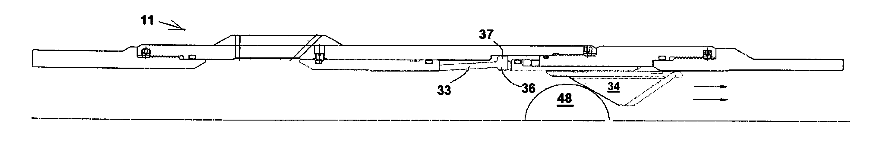
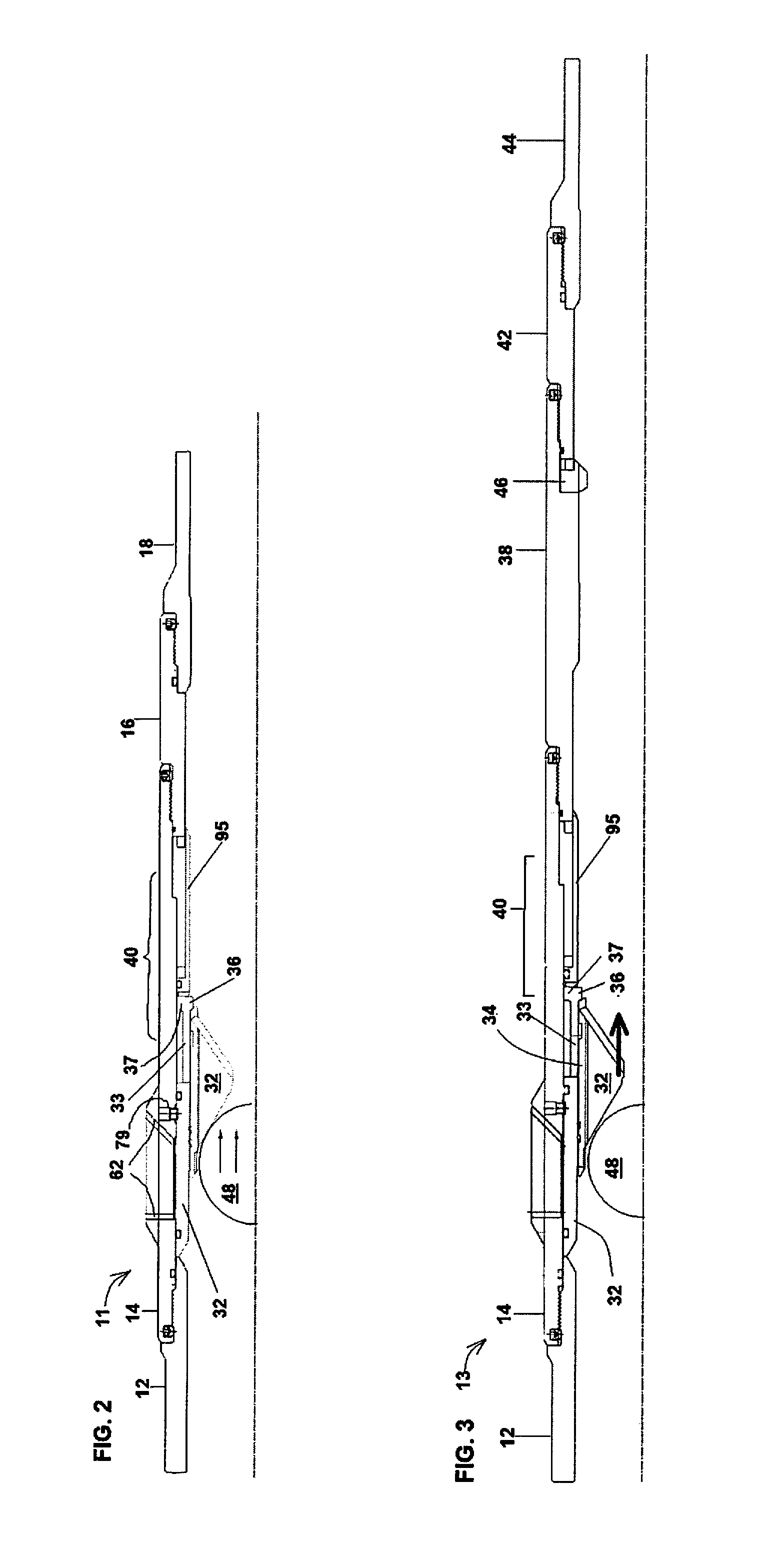
[0066]The cluster valve multi-stage liner 10 of the present invention, comprising at least one go valve 11 (and preferably and advantageously a plurality of go valves 11) and a single stop valve 13, can preferably be used in any oil and gas well after drilling. The liner 10 may also be used in other types of producing or injection wells.

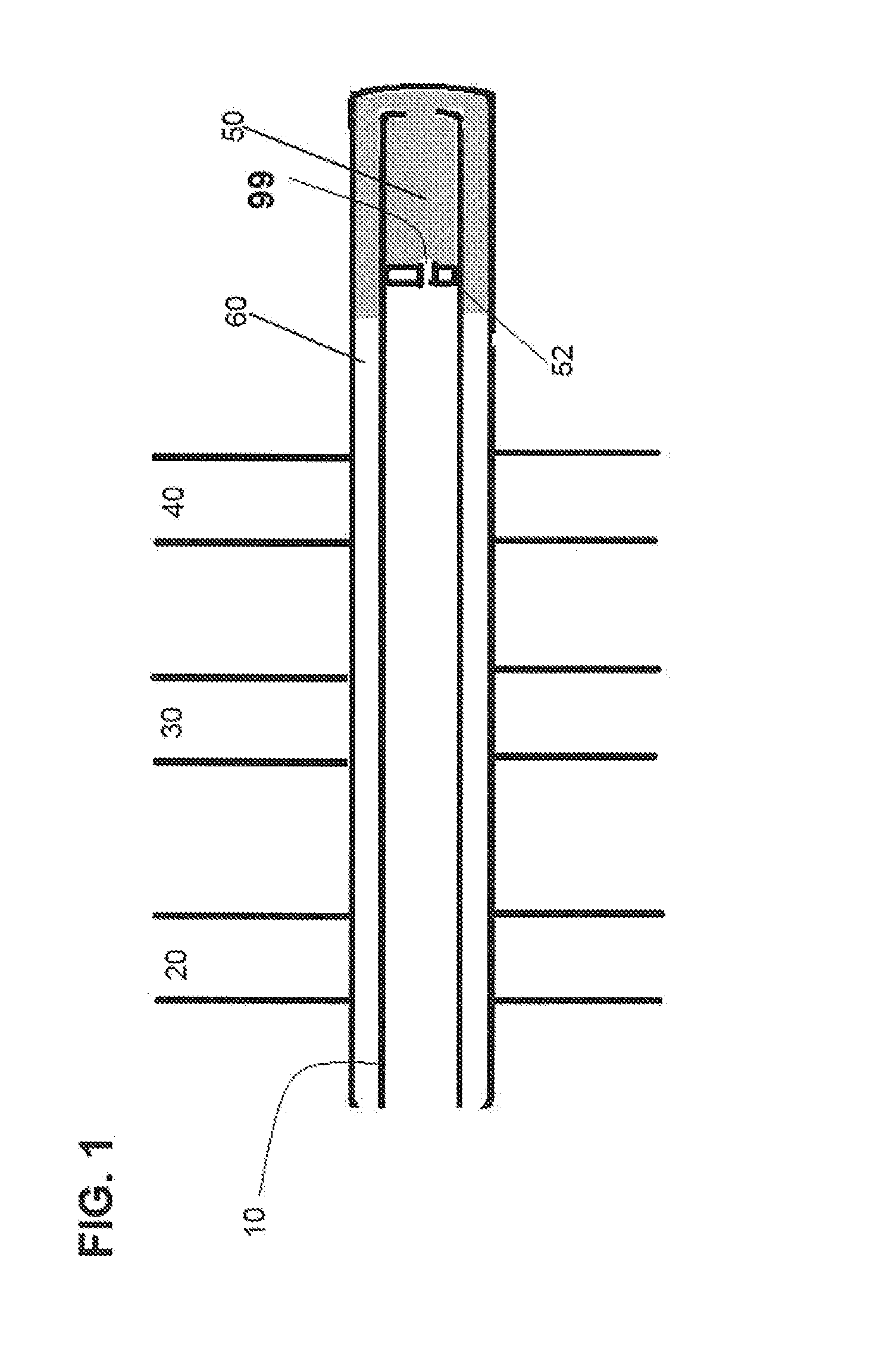
[0067]A typical configuration in a drilled well, whether it is partly cased or open hole, appears in FIG. 1. Liner 10 as been lowered on tubing from a service or drilling rig on surface, and inserted into the drilled well and positioned therein at a location therein, typically where the wellbore in a deviated well is horizontal., as shown. The liner 10 is used to isolate hydrocarbon zones 20, 30, 40 during fracture stimulations of a hydrocarbon formation in the region of said zones 20, 30, 40.

[0068]In FIG. 1, various hydrocarbon zones of interest are shown by r...


PUM


Abstract

A multi stage liner with cluster valves for completing and performing multiple fracture stimulations along a length of wellbore. Groups of cluster valves, with isolation between such groups of cluster valves, and a method of using same, are provided to achieve increased oil and gas flow to a wellbore in openhole or cased hole applications for oil and gas wells.

Description

FIELD OF INVENTION[0001]The present invention relates to cluster valves and multi-stage liners used in directional, including but not limited to horizontal oil and gas wells, either in open hole or cased completions to permit isolation between multiple hydrocarbon zones and to perform multiple fractures in the hydrocarbon zones.BACKGROUND OF THE INVENTION AND DESCRIPTION OF PRIOR ART[0002]This background information and publications mentioned below are provided for the purpose of making known information believed by the applicant to be of possible relevance to the present invention, and in particular allowing the reader to understand advantages of the invention over devices and methods known to the inventor, but not necessarily public, devices and methods. No admission is necessarily intended, nor should be construed as admitting, that any of the following documents constitute legally citable prior art against the present invention.[0003]After oil and gas wells are drilled, the oil ...

Claims


Application Information

Patent Timeline
Patent Type & Authority Applications(United States)
IPC IPC(8): E21B34/10E21B43/26E21B33/14E21B34/06E21B34/12
CPCE21B34/063E21B34/12E21B34/10E21B43/26E21B2034/007E21B33/146E21B34/14E21B2200/06E21B43/12E21B34/142
Inventor JANI, WILLIAM
Owner SC ASSET CORP
Why Eureka
Try Eureka