Self-pumping hydrodynamic mechanical seal

a mechanical seal and self-pumping technology, applied in the direction of engine seals, mechanical apparatus, engine components, etc., can solve the problems of increasing the failure rate of sealing, complicated seals, and large installation space, so as to reduce the operating cost of the pump, reduce the friction of the interface, and increase economic efficiency

Inactive Publication Date: 2016-04-07
NANJING FORESTRY UNIV
View PDF13 Cites 10 Cited by
  • Summary
  • Abstract
  • Description
  • Claims
  • Application Information

AI Technical Summary

Benefits of technology

[0025]5) Under a static state, the high-pressure side fluid is directly injected into the seal interface, which eliminates solid friction of the interface at a starting moment and rapidly form a fluid film separating the seal faces at the starting moment; therefore, the seal is also suitable for shaft seal

Problems solved by technology

Especially if the pumping medium comprises grains, the end face of the seal dam will be damaged, which accelerates the failure of sealing.
However, such se

Method used


Image

  • Self-pumping hydrodynamic mechanical seal
  • Self-pumping hydrodynamic mechanical seal
  • Self-pumping hydrodynamic mechanical seal

Examples


embodiment 1

Preferred Embodiment 1

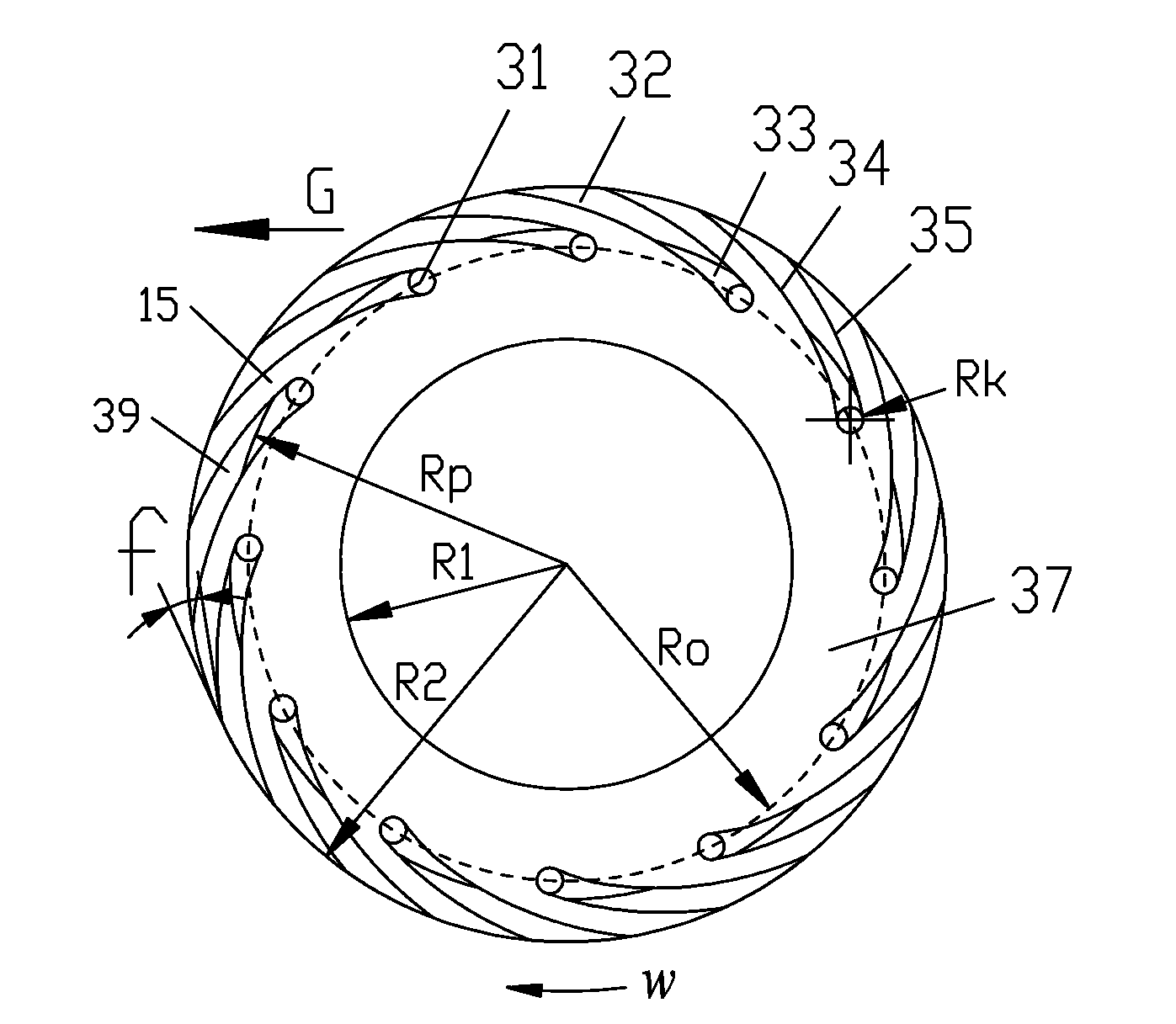
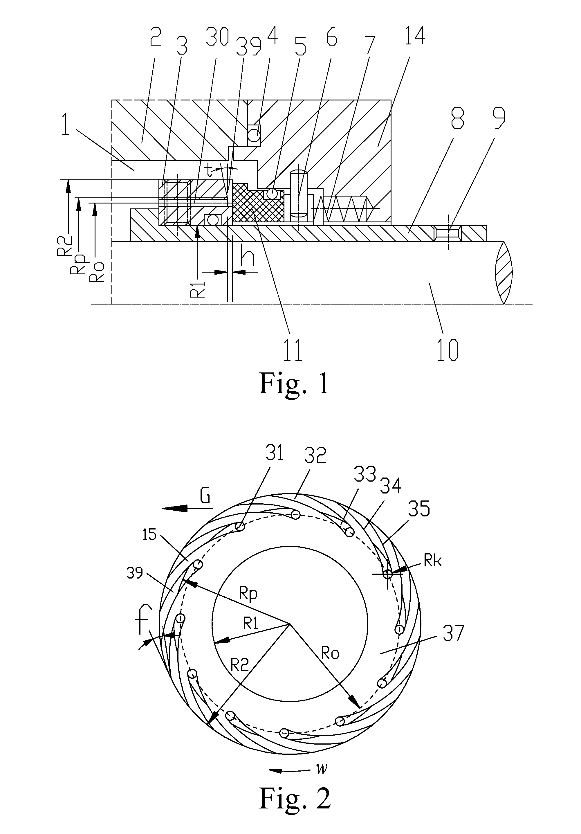
[0052]Referring to FIGS. 1 and 2, a self-pumping hydrodynamic mechanical seal is illustrated, which is provided between a shell 2 of a rotating machinery and a shaft 10 or a shaft sleeve 8, wherein the self-pumping hydrodynamic mechanical seal comprises a rotating ring 3; an O-ring for the rotating ring 12; a stationary ring 11; an O-ring for the stationary ring 5; a spring 7; and a stationary ring holder 14. An O-ring 4 is provided between the shell 2 and a stationary ring holder 14. The shaft sleeve 8 is mounted on the shaft 10 by a first fixing bolt 9. The rotating ring 3 is mounted on the shaft sleeve 8 by a second fixing bolt 13, and the O-ring for the rotating ring 12 is provided between the rotating ring 3 and the shaft sleeve 8. The stationary ring 11 is provided on the stationary ring holder 14, and the O-ring for the stationary ring 5 is provided between the stationary ring 11 and the stationary ring holder 14. A first end of a stop pin 6 is on the st...

embodiment 2

Preferred Embodiment 2

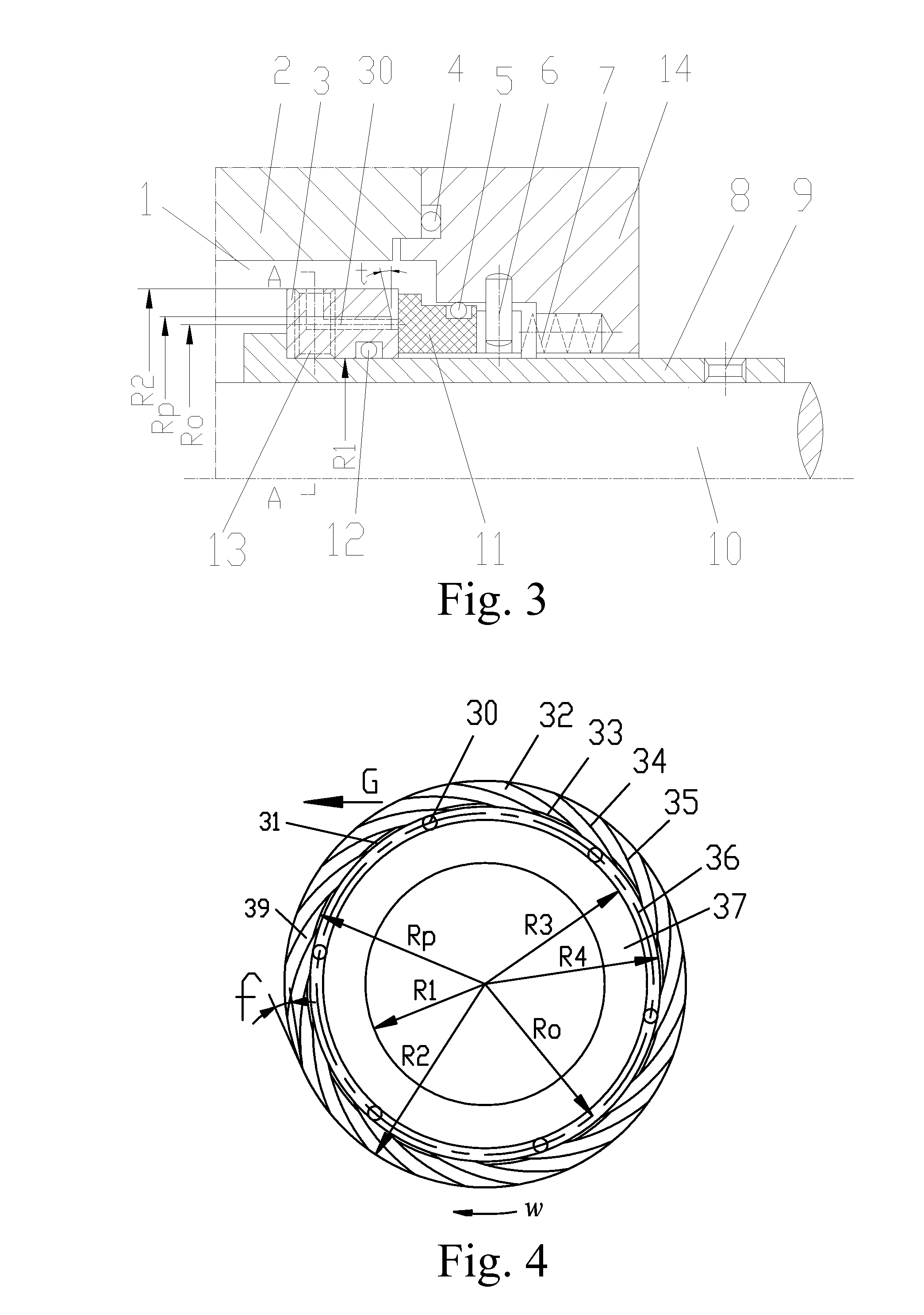
[0062]Referring to FIGS. 3-5, another self-pumping hydrodynamic mechanical seal is provided. Different from the preferred embodiment 1, the inlets 31 of the backward curved grooves 39 connects with a loop groove 36 at the middle portion of the seal face of the rotating ring 3, six axial-radial-combined ducts 30 connectting with the seal chamber 1 are provided on the loop groove 36; a cross section of a joint portion of the ducts 30 and an external round face of the rotating ring 3 is a wedge-shaped opening 38; the loop groove 36 has effects such as collecting the medium of self-lubricating and self-flushing, preventing the pumping medium from being non-uniform, and preventing the occurrence of cavitation when fluid supplement is not in time at the inlets 31 of the backward curved grooves 39.

[0063]Other structures of the preferred embodiment 2 are same as the preferred embodiment 1.

embodiment 3

Preferred Embodiment 3

[0064]Referring to FIGS. 6-8, self-pumping hydrodynamic mechanical seal is illustrated, which is provided between a shell 2 of a rotating machinery and a shaft sleeve 8, wherein the self-pumping hydrodynamic mechanical seal comprises a rotating ring 3; an O-ring for the rotating ring 12; a stationary ring 11; an O-ring for the stationary ring 5; a spring 7; and a stationary ring holder 14. An O-ring 4 is provided between the shell 2 and a stationary ring holder 14. The shaft sleeve 8 is mounted on the shaft 10 by a first fixing bolt 9. The rotating ring 3 is mounted on the shaft sleeve 8 by a second fixing bolt 13, and the O-ring for the rotating ring 12 is provided between the rotating ring 3 and the shaft sleeve 8. The stationary ring 11 is provided on the stationary ring holder 14, and the O-ring for the stationary ring 5 is provided between the stationary ring 11 and the stationary ring holder 14. A first end of a stop pin 6 is on the stationary ring holder...


PUM


Abstract

A self-pumping hydrodynamic mechanical seal includes a rotating ring (3) and a stationary ring (11). More than three sets of backward curved grooves (39) are provided on a seal face of the rotating ring (3), outlets of the backward curved grooves (39) are provided at an external diameter portion of the seal face of the rotating ring (3), and an inlet (31) connects with a seal chamber (1) through a duct (30) of the rotating ring (3) or the stationary ring (11). When the rotating ring (3) rotates, a medium in the backward curved grooves (39) is accelerated into a high-speed fluid; under a centrifugal force, the high-speed fluid moves to an external diameter side of the rotating ring (3), so as to be pumped into the seal chamber (1) and generates a low-pressure area at the inlets (31) of the backward curved grooves (39); the medium in the seal chamber (1) is driven by a pressure difference, so as to flow into the backward curved grooves (39) through the duct (30), for forming circulation of self-pumping. During pumping the high-speed fluid, a flow speed of the high-speed fluid is slowed and a pressure of the high-speed fluid is increased, as a flow sectional area of the backward curved grooves (39) is increased, so as to generate an opening force which separates the rotating ring (3) from the stationary ring (11). The seal has desirable capabilities of self-lubrication, self-flushing, solid particle interference resistance, and optimal sealing performance.

Description

CROSS REFERENCE OF RELATED APPLICATION[0001]This is a U.S. National Stage under 35 U.S.C 371 of the International Application PCT / CN2014 / 075791, filed Apr. 21, 2014, which claims priority under 35 U.S.C. 119(a-d) to CN 201310201473.3, filed May 28, 2013.BACKGROUND OF THE PRESENT INVENTION[0002]1. Field of Invention[0003]The present invention belongs to the field of sealing technology, and more particularly, deals with a self-pumping mechanical seal with hydrodynamic effect, which is applicable to various sealing shafts of rotating machinery such as compressors, centrifugal pumps and agitators of reaction still.[0004]2. Description of Related Arts[0005]Conventionally, non-contacting mechanical end face seal, which is widely used on equipment such as compressors, fans and centrifugal pumps in petroleum, chemical, chemical fiber, paper, power and metallurgical industries, is formed by drilling a groove on a sealing surface of the rotating ring, wherein a fluid dynamic wedge is formed a...

Claims


Application Information

Patent Timeline
IPC IPC(8): F16J15/34F16J15/00
CPCF16J15/002F16J15/3412F16J15/342
Inventor SUN, JIAJUNHU, QIONGZHOU, MINTU, QIAOANMA, CHENBOYU, BO
Owner NANJING FORESTRY UNIV
Why Eureka
Try Eureka