
Method and system for the vibration analysis of an engine

a technology of vibration analysis and engine, applied in the direction of engine testing, structural/machine measurement, instruments, etc., can solve the problems of difficult to obtain the vibration signature of the engine, wear and tear of the engine components, and the inability to transmit the measurements to the ground for a detailed analysis

Active Publication Date: 2016-04-14
SN DETUDE & DE CONSTR DE MOTEURS DAVIATION S N E C M A
View PDF3 Cites 14 Cited by
  • Summary
  • Abstract
  • Description
  • Claims
  • Application Information

AI Technical Summary

Benefits of technology

The patent describes a method to quickly and automatically analyze the vibration behavior of new engines. The method allows for easy access to data of similar engines, which can help detect or predict issues with the engine. The analysis uses spectral images, which are then compared to find the closest match. This helps to improve diagnostic accuracy. The method also allows for updating and enriching of a reference database with new data. Overall, the invention allows for efficient and cost-effective engine analysis.

Problems solved by technology

An engine is subjected to mechanical stresses which can result in the wear and tear of its elements.
However, the vibration signature of the engine is very difficult to obtain as it comes from accelerometric and tachometric measurements acquired at a very high frequency (of a magnitude of 50 kHz).
Such measurements cannot be transmitted to the ground for a detailed analysis and the algorithms currently onboard seek only known models and are not validated on operations in actual operation.
It often occurs that such algorithms appear to be ineffective as the conditions for acquiring data are not those that were hoped for when the algorithm was designed.
Moreover, the implementing of an algorithm on an onboard calculator of an engine in a complex and expensive process, and such the tendency is to construct general algorithms that calibrate themselves on a family of engines and are not suited to a specific engine.
Furthermore, the onboard calculators are not currently able to adapt an algorithm on the fly, and the certification processes for such intelligent tools are not yet defined.
For example, during the study of a given spectrogram, a zone may appear to the expert as being atypical and therefore deemed as suspicious because it is highly unlikely.
The work of the comparison is complex, meticulous and strongly linked to the analysis and to its operation experience.
One of the difficulties of this work is that it is not possible to define a unique reference spectrogram.

Method used


Image

  • Method and system for the vibration analysis of an engine
  • Method and system for the vibration analysis of an engine
  • Method and system for the vibration analysis of an engine

Examples


Embodiment Construction

[0042]The principle of the invention consists in implementing a metric adapted to compare a spectral window of an engine to be analysed with spectral windows relating to other engines, contained in a reference database. This makes it possible to make the best use of the reference database and in an automatic manner.

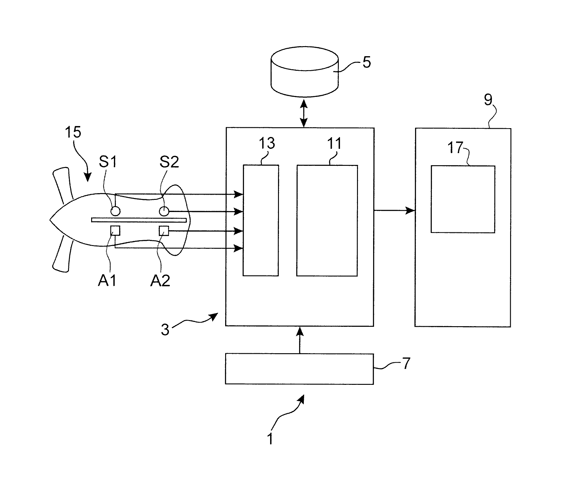
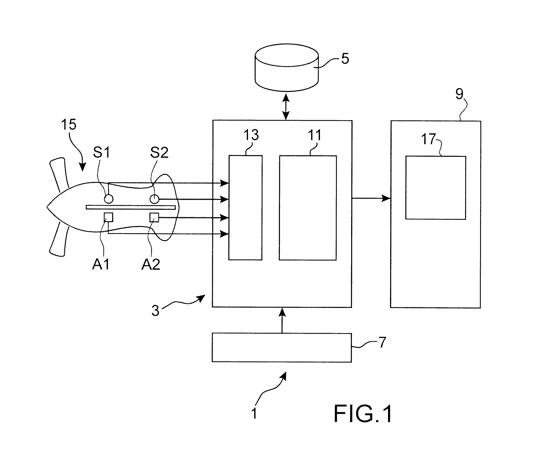
[0043]FIG. 1 shows an example of material means implemented in the system or method for the vibration analysis of an engine and more particularly of an aircraft engine, according to the invention.

[0044]The system 1 for the vibration analysis comprises processing means 3, storage means 5, input means 7, and output means 9.

[0045]The processing means 3 comprises calculating means 11 as well as acquisition means 13 for acquiring signals coming from sensors A1, A2, S1, S2 installed in the engine 15.

[0046]Indeed, sensors of vibration, speed, temperatures, pressure, etc. are integrated into the aircraft engine 15 in order to collect over the course of time measurements on variab...


PUM


Abstract

A method and a system for the vibration analysis of an engine, including acquiring vibration signals relating to the engine and in order to form at least one spectrogram that represents an operating state of the engine, selecting at least one zone of interest in at least one spectrogram, comparing each zone of interest with a set of corresponding comparison zones belonging to annotated spectrograms recorded in a reference database, and determining a subset of comparison zones that have vibration behaviours similar to those of the zone of interest, and displaying the subset of comparison zones and annotations associated with the subset of comparison zones.

Description

FIELD OF THE INVENTION[0001]This invention relates to the field of engine monitoring. In particular, the invention relates to a method and a system for the vibration analysis of an engine in order to detect anomalies or predict the behaviour of the engine.[0002]An engine is subjected to mechanical stresses which can result in the wear and tear of its elements. An effective way to monitor the condition of an engine or its future behaviour is to measure its vibration signature which represents one of the fundamental characteristics of the engine.[0003]More particularly, in the case of an aircraft engine, vibration sensors of the accelerometer type are used in order to measure the vibrations emitted by the engine. However, the vibration signature of the engine is very difficult to obtain as it comes from accelerometric and tachometric measurements acquired at a very high frequency (of a magnitude of 50 kHz). Such measurements cannot be transmitted to the ground for a detailed analysis ...

Claims


Application Information

Patent Timeline
Patent Type & Authority Applications(United States)
IPC IPC(8): G01M15/12
CPCG01M15/12G05B23/0229
Inventor LACAILLE, JEROME
Owner SN DETUDE & DE CONSTR DE MOTEURS DAVIATION S N E C M A
Learn More