Gas generator

a generator and gas technology, applied in the direction of respirator, treatment control/steering, treatment water, etc., can solve the problems of energy consumption problems, experience lung damage and lung damage, and the efficiency of electrolyzing to be decreased

Active Publication Date: 2016-04-21
LIN HSIN YUNG
View PDF19 Cites 21 Cited by
  • Summary
  • Abstract
  • Description
  • Claims
  • Application Information

AI Technical Summary

Benefits of technology

[0007]Therefore, an aspect of the present invention is to provide a gas generator, which electrolyzes liquid water and generates hydrogen-oxygen mixed gas. Meanwhile, the gas generator of the present invention can maintain the quantity of the hydrogen-oxygen mixed gas in the water tank, and cool down the temperature of the hydrogen-oxygen mixed gas as well, to avoid gas explosions.

Problems solved by technology

However, most of the treatments in the past are passive, which means that they only treat the disease when the disease occurs.
Furthermore, there are also clinical experiments showing that patients who need to inhale a high concentration of oxygen for an extended period of time would experience lung damage and the lung damage, and they could be ameliorated by inhaling hydrogen.
However, it's easy to generate high temperature in the electrolyzing process, which will allow the efficiency of electrolyzing to be decreased and cause energy consumption problems.
However, if the fan malfunctions, the temperature of the electrolysis tank will be raised, and it's easy to cause hydrogen explosions.

Method used


Image

  • Gas generator
  • Gas generator
  • Gas generator

Examples


third embodiment

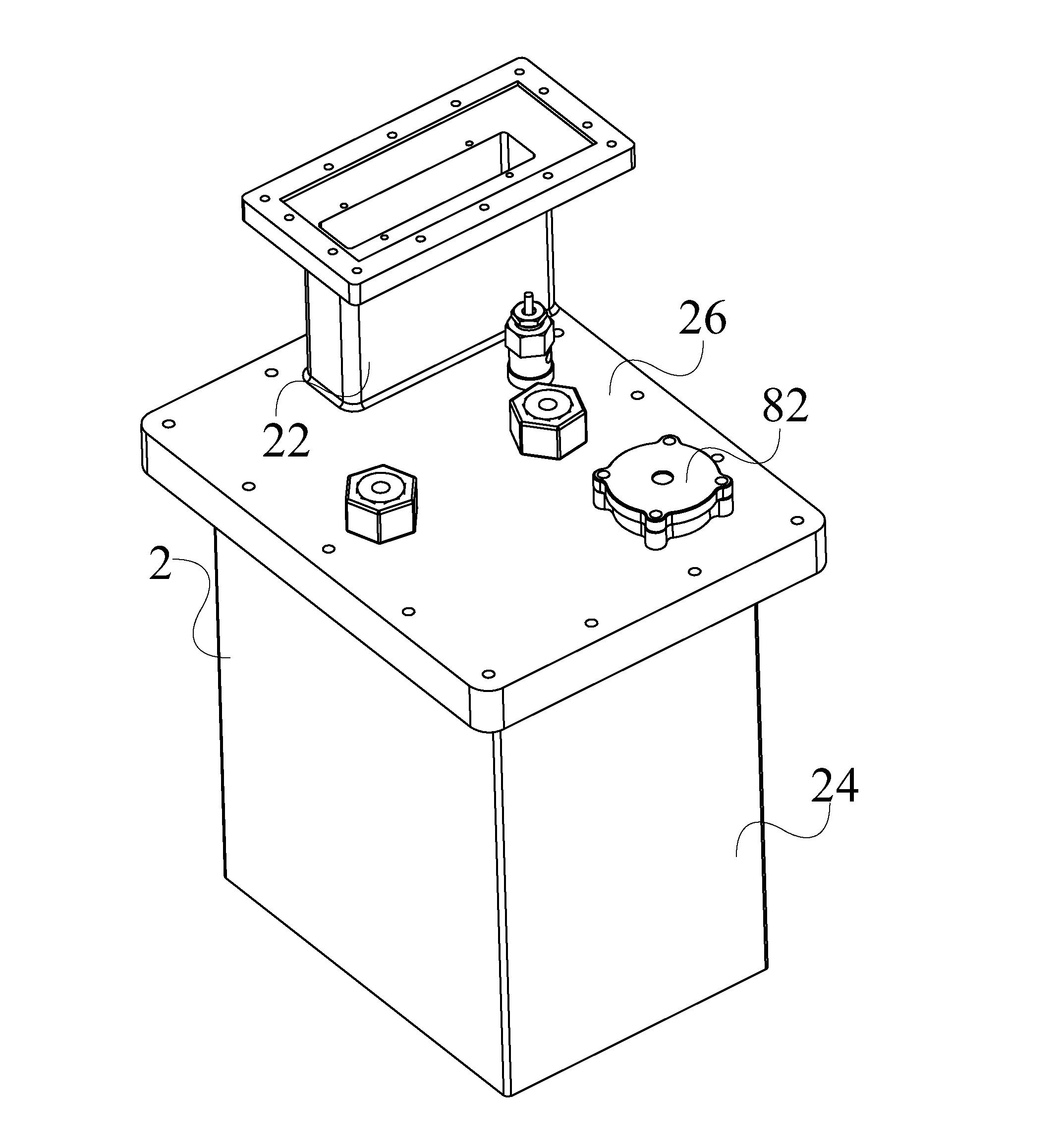
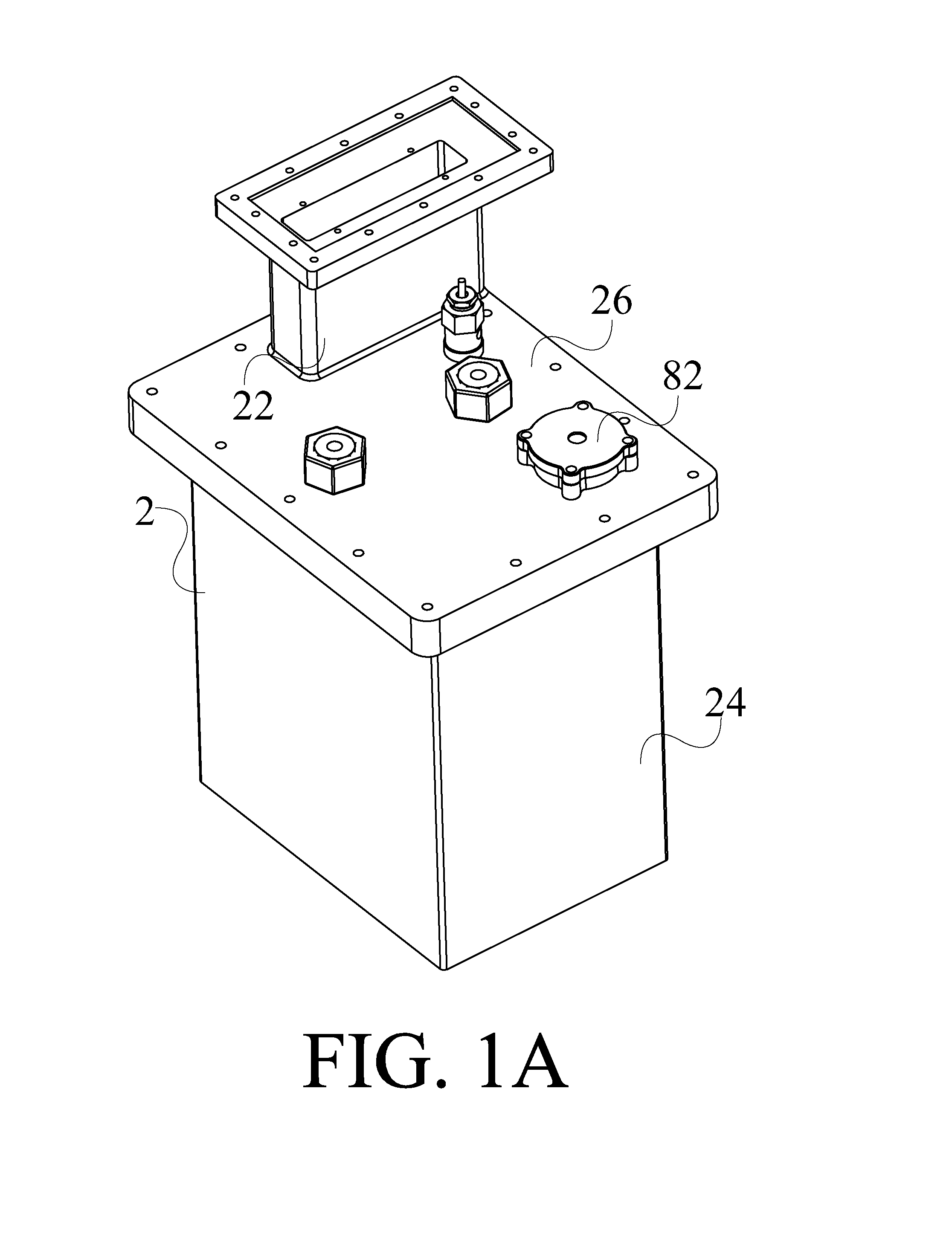
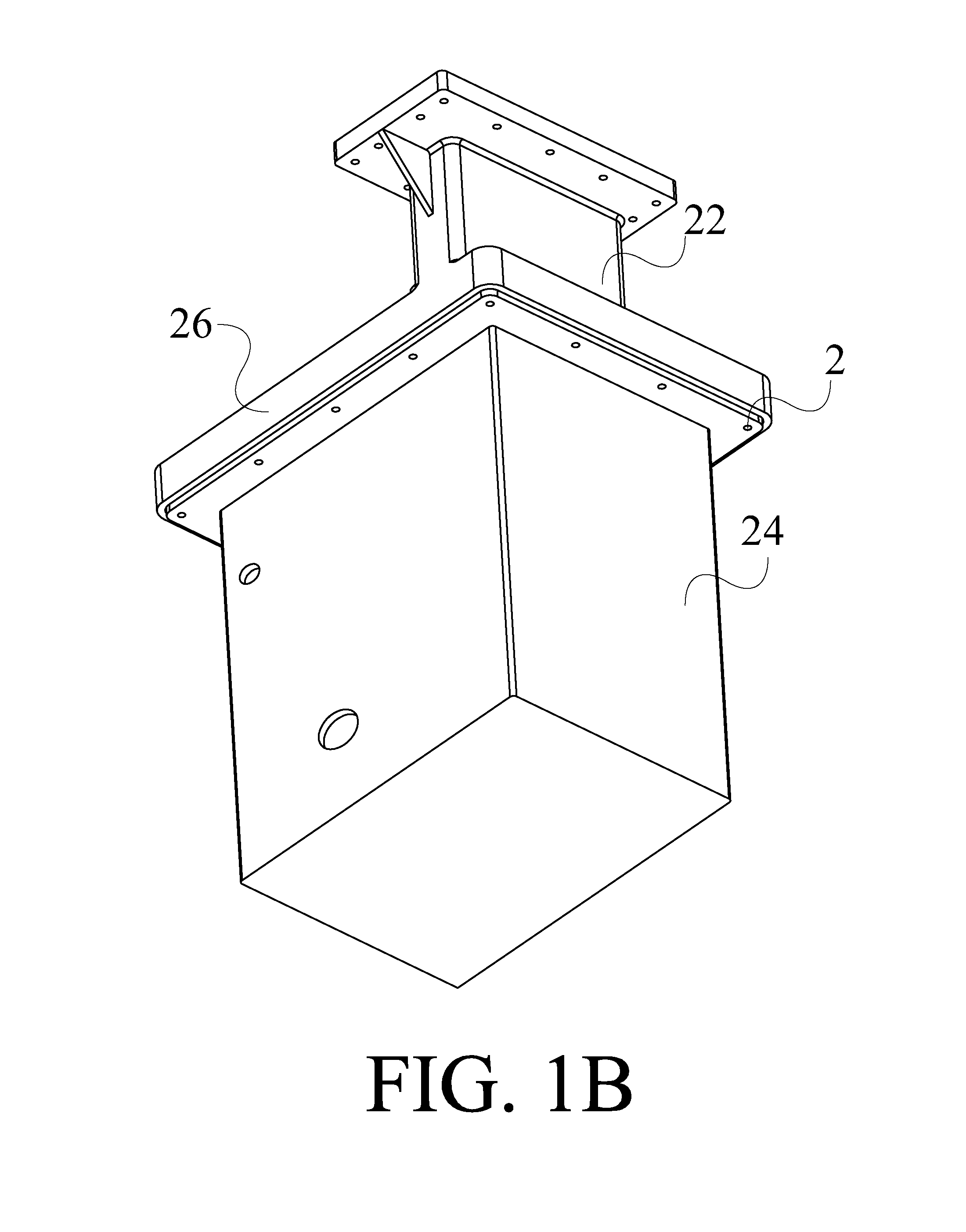
[0083]Additionally, in the third embodiment, the gas generator 1 of the present invention further comprises a nebulized gas mixing tank 4 (as shown in FIG. 15A). The nebulized gas mixing tank 4 can be coupled to the electrolysis device 3 for receiving the hydrogen-oxygen mixed gas G. The nebulized gas mixing tank 4 can generate a nebulized gas G2 and be mixed with the hydrogen-oxygen mixed gas G to form a healthy gas for user to breathe. In practical application, the nebulized gas G2 can be selected from a group consisting of water vapor, nebulized medicinal liquid, evaporated essential oil, and the combination thereof.

[0084]After explaining the design of each element in the statement mentioned above, the following statement will describe the combination method and the application of each element of the gas generator of the present invention.

[0085]In the electrolysis device 3 which is assembled completely, plurality of electrodes is disposed with space in the electrolysis tank 32, t...

fourth embodiment

[0093]Please refer to FIG. 17. In the fourth embodiment, the present invention further provides a gas generator, which has function of controlling the temperature of the electrolyzed water and cooling down the electrolyzed water after generated hydrogen-oxygen mixed gas. In this embodiment, the gas generator 1 comprises an electrolysis device 3, a water pump 5, and a cooling device 7. The electrolysis device 3 contains an electrolyzed water W. The electrolysis device 3 is used to electrolyze the electrolyzed water W to generate a hydrogen-oxygen mixed gas G. The cooling device 7 is connected to the electrolysis device 3, used to cool down the electrolyzed water W after the hydrogen-oxygen mixed gas G is generated. The water pump 5 is connected between the cooling device 7 and the electrolysis device 3, used to enforce to circulate the electrolyzed water W.

[0094]Please refer to FIG. 17. FIG. 17 shows a schematic diagram of the gas generator in the fifth embodiment of the present inve...

sixth embodiment

[0095]Additionally, in the sixth embodiment, the gas generator 1 of the present invention further comprises a nebulized gas mixing tank 4 (as shown in FIG. 15A). The nebulized gas mixing tank 4 can generates a nebulized gas G2 and be mixed with the hydrogen-oxygen mixed gas G to form a healthy gas for a user to breathe.

[0096]The following statement will explain the design of each element of the present invention respectively.

[0097]The designs of the structures of the water tank 2, the electrolysis device 3, the water pump 5, and the nebulized gas mixing tank 4 have been explained in the statements mentioned above, so unnecessary details will not be given again herein.

[0098]Please refer to FIG. 15A, FIG. 15B, and FIG. 17. In the fourth embodiment, the cooling device 7 of the present invention comprises a radiator 70 and a fan 72. The radiator 70 comprises a box 700 and a radiating tube 702. The radiating tube 702 is disposed in the box 700 of the radiator 70. The shape of the radiati...


PUM

PropertyMeasurementUnit
temperatureaaaaaaaaaa

Abstract

The present invention provides a gas generator, comprising a water tank and an electrolysis device. The water tank has a first hollow portion for containing electrolyzed water. The electrolysis device is disposed inside the first hollow portion of the water tank for electrolyzing the electrolyzed water to generate a hydrogen-oxygen mixed gas. When the electrolysis device starts to electrolyze the electrolyzed water, the first hollow portion of the water tank is filled with the electrolyzed water for standing at a full level of water. And after the electrolysis device electrolyzed the electrolyzed water, the level of water for the electrolyzed water filled into the first hollow portion of the water tank is higher than 95% of the full level of water. The gas generator of the present invention provides the design for saving space and nearly a zero gas chamber to reduce the possibility of explosions resulting from hydrogen-oxygen mixed gas.

Description

PRIORITY CLAIM[0001]This patent application claims priority from TW Patent Application. No. 103135890 filed Oct. 16, 2014, TW Patent Application. No. 103135889 filed Oct. 16, 2014, TW Patent Application. No. 103135892 filed Oct. 16, 2014, TW Patent Application. No. 103135891 filed Oct. 16, 2014 and TW Patent Application. No. 103135877 filed Oct. 16, 2014. Each of the foregoing applications are hereby incorporated by reference in their entirety as if fully set forth herein.FIELD OF THE INVENTION[0002]The present invention relates to a gas generator, and more particularly, the present invention relates to a gas generator which can prevent explosions and has function of controlling the temperature of the electrolyzed water and cooling down the electrolyzed water after generated hydrogen-oxygen mixed gas.DESCRIPTION OF THE PRIOR ART[0003]People are always paying a great deal of attention on health developments. Many developments in medical technology are often targeted on treating disea...

Claims


Application Information

Patent Timeline
Patent Type & Authority Applications(United States)
IPC IPC(8): C25B1/04C25B15/02C25B9/17
CPCC25B15/02C25B1/04A61M16/14C02F1/008C02F1/36C02F1/4618A61M2202/0208C02F2001/46152C02F2103/026C02F2201/46155C02F2209/005C02F2209/02C02F2209/38C02F2209/40C02F2209/42C02F2303/16A61M11/06A61M15/08A61M16/101C25B15/08A61M16/107Y02E60/36A61M2202/0007C25B11/02C25B9/13C25B1/044C25B11/00Y02E60/32
Inventor LIN, HSIN-YUNG
Owner LIN HSIN YUNG
Why Eureka
Try Eureka