Method and Apparatus for Monitoring Energy Consumption

a technology of energy consumption and monitoring method, applied in the direction of power measurement by digital technique, measurement devices, instruments, etc., can solve the problems of coarse-grained energy consumption measurement, difficult (if not impossible) to directly quantize the delivered output current, and the inability to manage power consumption in near real-time. the effect of small utility

Active Publication Date: 2016-04-21
AMBIQ MICRO
View PDF13 Cites 3 Cited by
  • Summary
  • Abstract
  • Description
  • Claims
  • Application Information

AI Technical Summary

Benefits of technology

This example of a patent describes a new invention that solves a problem. The technical effect of this invention is to provide a better solution to an existing problem.

Problems solved by technology

Furthermore, it is of no relevance in such systems which specific voltage levels are selected to represent each of the logic states.
In either form of power supply, linear regulator or buck converter, it is difficult (if not impossible) to directly quantize the delivered output current using circuits amenable to integration into a single IC.
However, such approaches are relatively gross and provide, at best, very coarse-grained energy consumption measurements, which are of little utility in managing power consumption is near real-time.

Method used


Image

  • Method and Apparatus for Monitoring Energy Consumption
  • Method and Apparatus for Monitoring Energy Consumption
  • Method and Apparatus for Monitoring Energy Consumption

Examples


Embodiment Construction

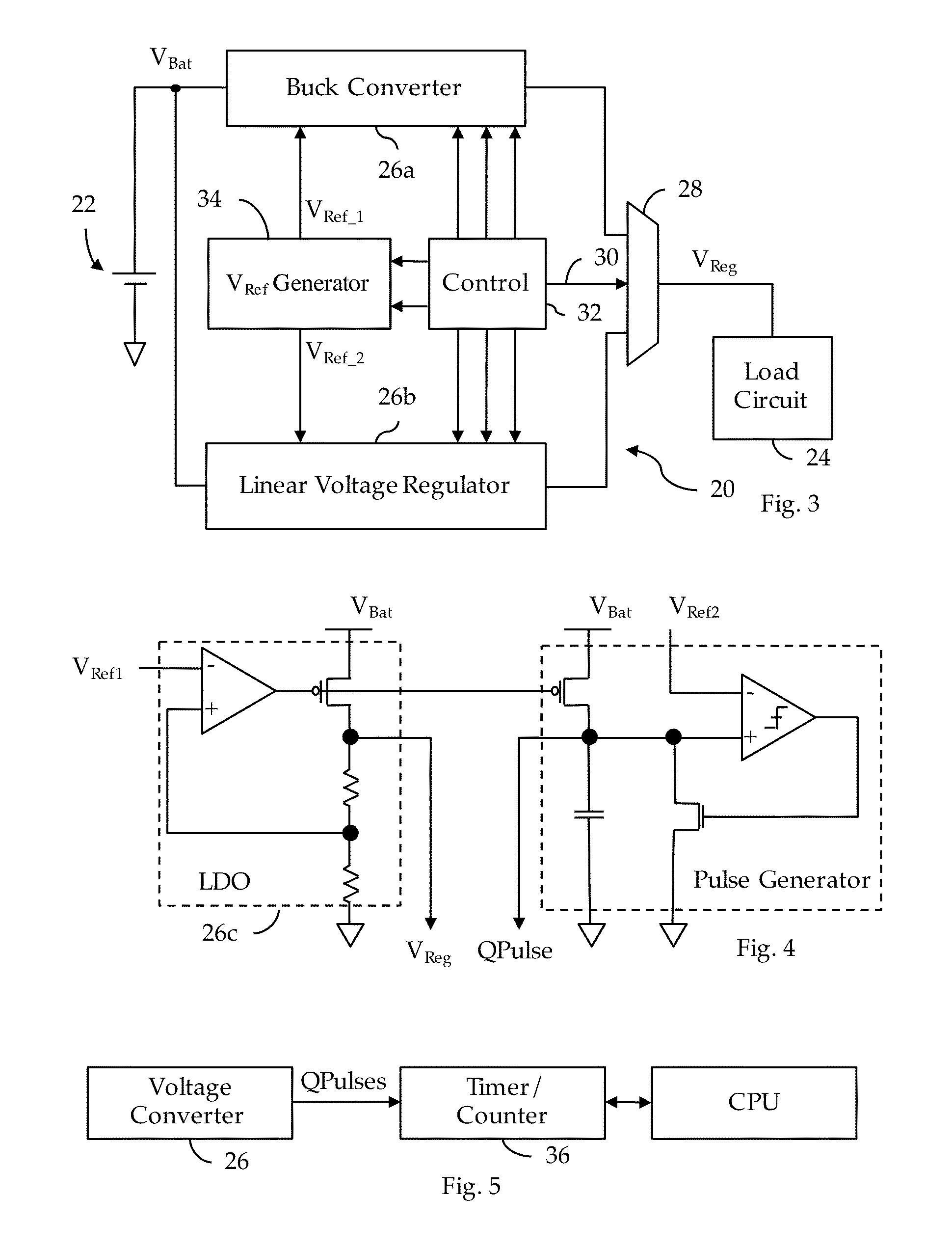
[0036]In the Related Application 1, an adaptive voltage converter 20 was disclosed comprising a buck converter 26a and a linear voltage regulator 26b (see, FIG. 3). In accordance with one embodiment of the present invention, buck converter 26a is adapted to provide a pulse, QPulse, each time a unit of charge is delivered to the load circuits 24, where a pulse is typically delineated either by its leading or trailing edge. Preferably, each pulse of the QPulse signal corresponds to the transfer of a fixed amount of charge from buck converter 26a to the load circuits 24. One known buck converter can be seen in FIG. 1 (Prior Art) of U.S. Pat. No. 5,006,782, expressly incorporated herein by reference; in this prior art circuit, the output of duty cycle control 18 coupled to the gate of switching transistor 12 would be suitable for use in the present method as the QPulse signal. Shown in FIG. 4 is an embodiment of a low-drop-out (“LDO”) linear regulator 26c which can be combined with a pu...


PUM


Abstract

An energy consumption monitor for use in an electronic system comprising an integrated circuit such as a microcontroller. The monitor comprises a counter adapted to accumulate pulses developed by a charge source, each pulse indicative of the delivery of one unit of charge to a load circuit. A monitoring facility monitors the counter to develop an energy consumption record over time.

Description

CROSS REFERENCE TO RELATED APPLICATIONS[0001]This application is related to the following:[0002]1. Provisional Application Ser. No. 62 / 066,218, filed 20 Oct. 2014 (“Parent Provisional”);[0003]2. PCT Application No. PCT / US15 / 50239 filed 15 Sep. 2015 (“Related Application 1”);[0004]3. U.S. application Ser. No. 14 / 855,105, filed 15 Sep. 2015 (“Related Application 2”);[0005]4. U.S. application Ser. No. [Docket No. JAM010], filed simultaneously herewith (“Related Application 3”);[0006]5. U.S. Application No. [Docket No. JAM012], file simultaneously herewith (“Related Application 4”); and[0007]6. U.S. Application No. [Docket No. JAM015], filed simultaneously herewith (“Related Application 5”).[0008]This application claims priority to the Parent Provisional, and hereby claims benefit of the filing date thereof pursuant to 37 CFR §1.78(a)(4).[0009]The subject matter of the Parent Provisional and the Related Applications, each in its entirety, is expressly incorporated herein by reference.BA...

Claims


Application Information

Patent Timeline
Patent Type & Authority Applications(United States)
IPC IPC(8): G01R21/127
CPCG01R21/127G01R21/133
Inventor HANSON, SCOTTSHEAFOR, STEPHEN JAMESBAKER, DAVID CURETON
Owner AMBIQ MICRO
Why Eureka
Try Eureka