Vacuum cleaner with motor cooling

a vacuum cleaner and motor cooling technology, applied in the field of vacuum cleaners, can solve the problems of clogging bearings, affecting the life of electric motors, and affecting the operation of vacuum cleaners, etc., and achieve the effects of reducing flow losses, compact arrangement, and large volum

Inactive Publication Date: 2016-04-28
DYSON TECH LTD
View PDF23 Cites 18 Cited by
  • Summary
  • Abstract
  • Description
  • Claims
  • Application Information

AI Technical Summary

Benefits of technology

[0018]Where the first dirt-separation stage comprises a cyclonic separator, the cyclonic separator may have a central axis about which air within the cyclonic separator rotates. The vacuum motor may then comprise a rotational axis about which the impeller rotates, and the central axis and the rotational axis may be coincident. As a consequence, a relatively straight path may then be taken by the air as it moves from the further dirt-separation stage to the vacuum motor, thus reducing flow losses.
[0019]The dirt-separation stage may comprise a dirt collector, the further dirt-separation stage may comprise a further dirt collector, and the further dirt collector may surround the dirt collector. As a result, a relatively compact arrangement may be realised. The further dirt-separation stage may be used to remove relatively coarse dirt whilst the dirt-separation stage may be used to remove relatively fine dirt. Since the further dirt collector surrounds the dirt collector, a relatively large volume may be achieved for the further dirt collector whilst maintaining a relatively compact overall size.

Problems solved by technology

If the vacuum cleaner as a whole were located upstream of the dirt-separation stage and if the air drawn into the vacuum motor were used to cool the electric motor, the dirt carried by the air may damage or otherwise shorten the lifespan of the electric motor.
For example, the dirt may clog bearings or cover thermally-sensitive electrical components.

Method used


Image

  • Vacuum cleaner with motor cooling
  • Vacuum cleaner with motor cooling
  • Vacuum cleaner with motor cooling

Examples


Embodiment Construction

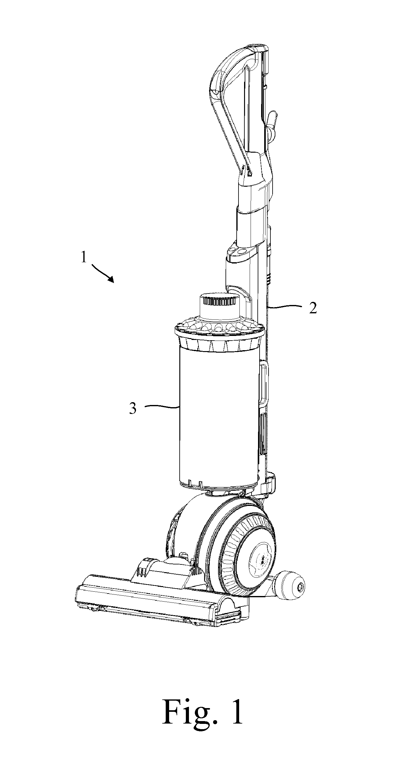
[0028]The vacuum cleaner 1 of FIG. 1 comprises a main body 2 to which a dirt separator 3 is removably attached.

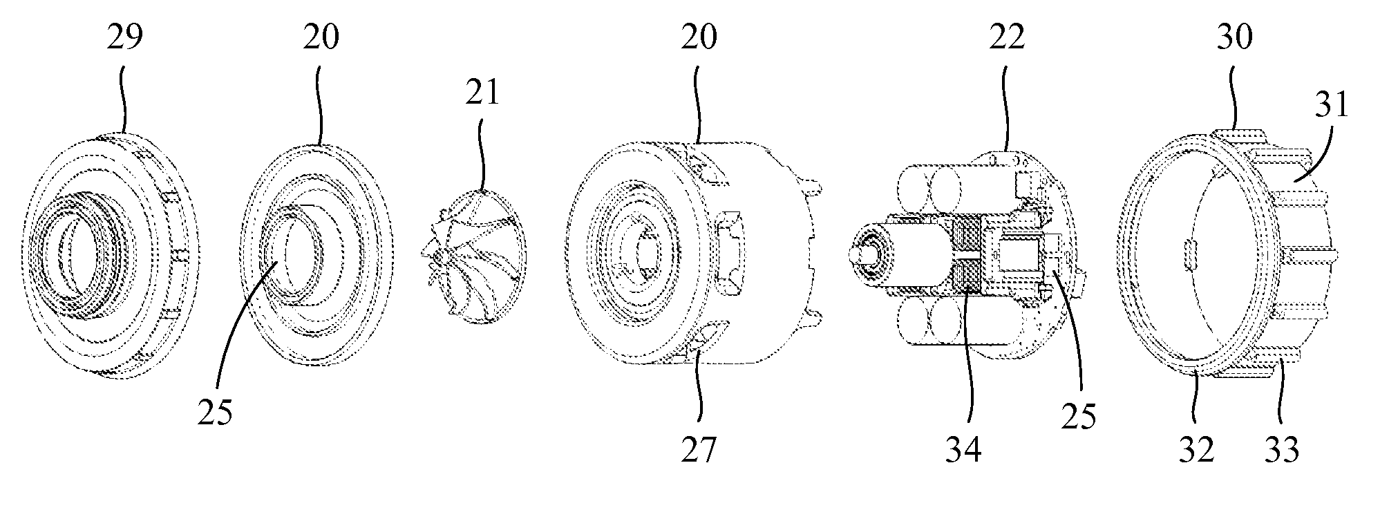
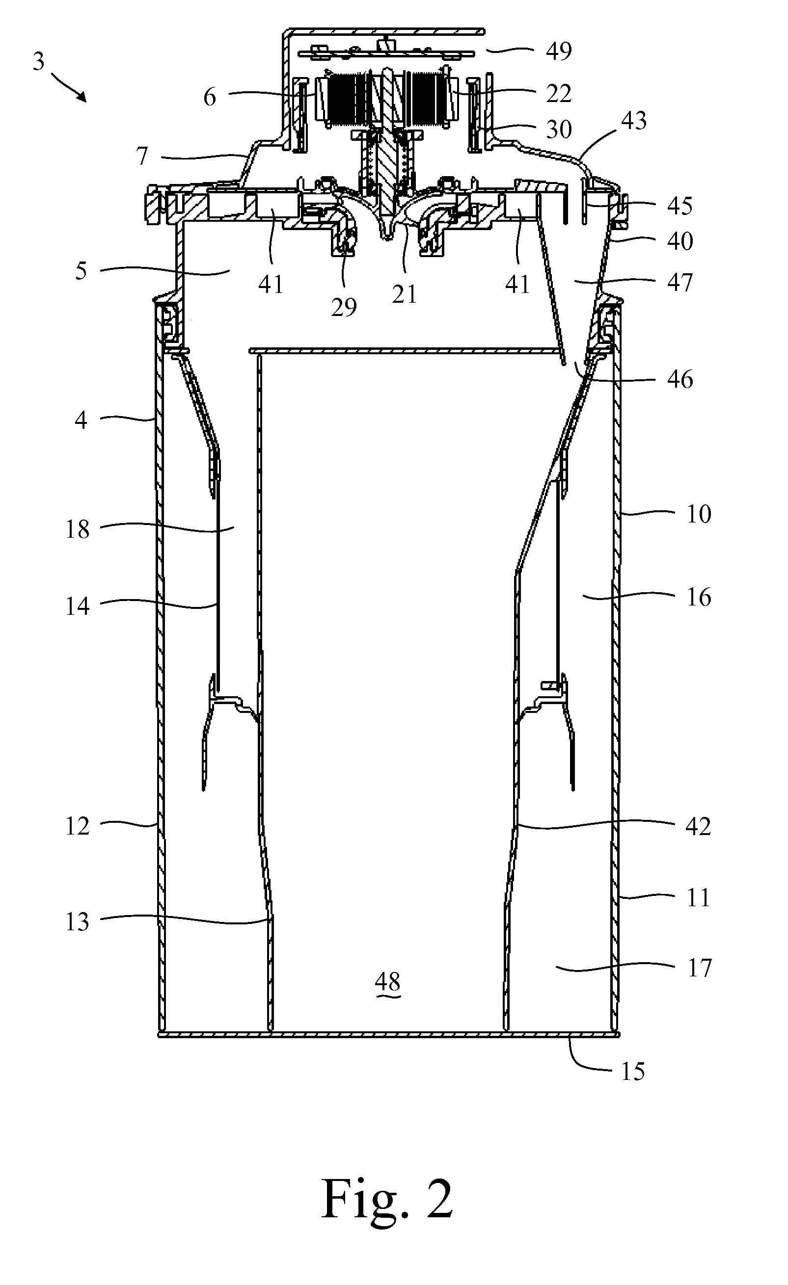
[0029]Referring now to FIGS. 2 to 7, the dirt separator 3 comprises a first dirt-separation stage 4, a motor plenum 5, a vacuum motor 6, and a second dirt-separation stage 7.

[0030]The first dirt-separation stage 4 comprises a cyclonic separator 10 and a dirt collector 11. The cyclonic separator 10 and the dirt collector 11 are defined by an outer wall 12, an inner wall 13, a shroud 14, and a base 15. The outer wall 12 is cylindrical in shape and surrounds the inner wall 13 and the shroud 14. The inner wall 13 is generally cylindrical in shape and is arranged concentrically with the outer wall 12. The upper part of the inner wall 13 is fluted, with the flutes providing passageways along which dirt separated by the cyclonic separators 40 of the second dirt-separation stage 7 are guided to a further dirt collector 42. The shroud 14 is located between the outer wall 12 and the ...


PUM


Abstract

A vacuum cleaner having a dirt-separation stage and a vacuum motor for moving air through the dirt-separation stage. The vacuum motor includes an impeller driven by an electric motor. The impeller is then located upstream of the dirt-separation stage, the electric motor is located downstream of the dirt-separation stage, and at least part of the air discharged from the dirt-separation stage is used to cool the electric motor.

Description

REFERENCE TO RELATED APPLICATION[0001]This application claims priority of United Kingdom Application No. 1418795.9, filed Oct. 22, 2014, the entire contents of which are incorporated herein by reference.FIELD OF THE INVENTION[0002]The present invention relates to a vacuum cleaner having a motor that is cooled by air discharged from a dirt-separation stage.BACKGROUND OF THE INVENTION[0003]A vacuum cleaner typically comprises a vacuum motor that pulls dirt-laden air through one or more dirt-separation stages. The dirt-separation stages are typically located upstream of the vacuum motor in order to protect the vacuum motor from the dirt carried by the air. After passing through the dirt-separation stages, the cleansed air may be drawn through the interior of the vacuum motor in order to cool the motor.SUMMARY OF THE INVENTION[0004]The present invention provides a vacuum cleaner comprising a dirt-separation stage and a vacuum motor for moving air through the dirt-separation stage, where...

Claims


Application Information

Patent Timeline
Patent Type & Authority Applications(United States)
IPC IPC(8): A47L9/28A47L5/22A47L9/16H02K9/06
CPCA47L9/2889H02K9/06A47L9/165A47L9/1616A47L5/22A47L9/1608A47L9/00A47L9/1633A47L9/1641A47L9/22A47L5/28A47L7/04A47L9/16A47L9/28
Inventor BOX, CHARLES GEOFFREYJOHNSON, MARK ANDREW
Owner DYSON TECH LTD
Why Eureka
Try Eureka