Circuit for de-icing an air inlet lip of an aircraft propulsion assembly

a propulsion assembly and air inlet technology, applied in the direction of efficient propulsion technologies, machines/engines, liquid fuel engines, etc., can solve the problem that the heating of said aircraft is not necessarily sufficient to ensure de-icing, and achieve the effect of reducing pressure loss, improving heat exchange, and increasing heat dissipation

Inactive Publication Date: 2016-04-28
SN DETUDE & DE CONSTR DE MOTEURS DAVIATION S N E C M A
View PDF8 Cites 19 Cited by
  • Summary
  • Abstract
  • Description
  • Claims
  • Application Information

AI Technical Summary

Benefits of technology

[0016]The invention thus proposes de-icing the air inlet lip by means of a heat transfer fluid which is heated by the lubrication oil of the engine. Firstly, this makes it possible to reduce the loss in pressure related to the bleeding of air at the engine required in the prior art to ensure the de-icing function. Secondly, this allows heat exchanges which promote the cooling of the lubrication oil, which can be very hot after it has lubricated elements of the engine such as bearings or equipment. Said hea

Problems solved by technology

The heat exchanges can be designed in such a way that said

Method used


Image

  • Circuit for de-icing an air inlet lip of an aircraft propulsion assembly
  • Circuit for de-icing an air inlet lip of an aircraft propulsion assembly
  • Circuit for de-icing an air inlet lip of an aircraft propulsion assembly

Examples


Embodiment Construction

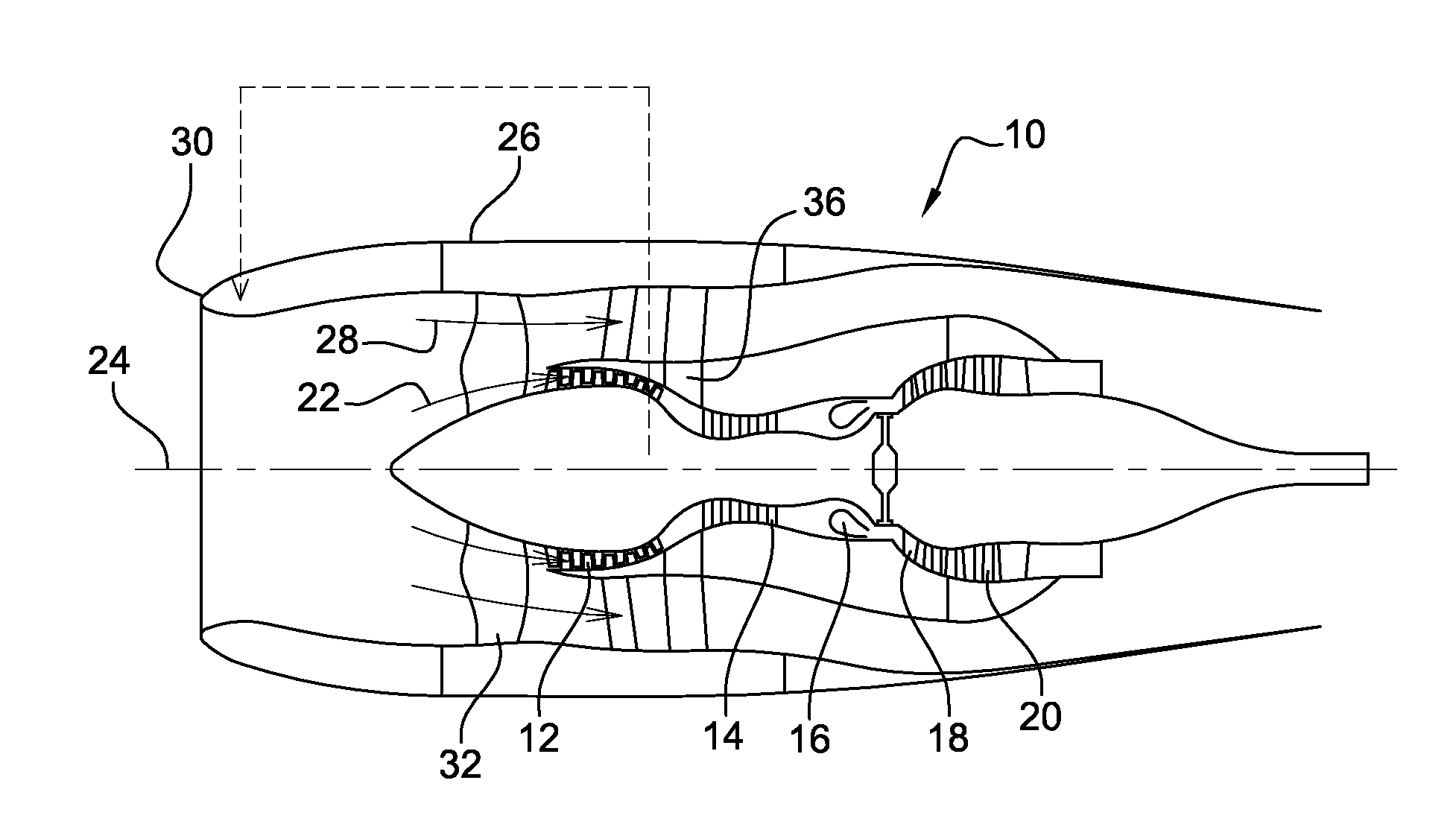
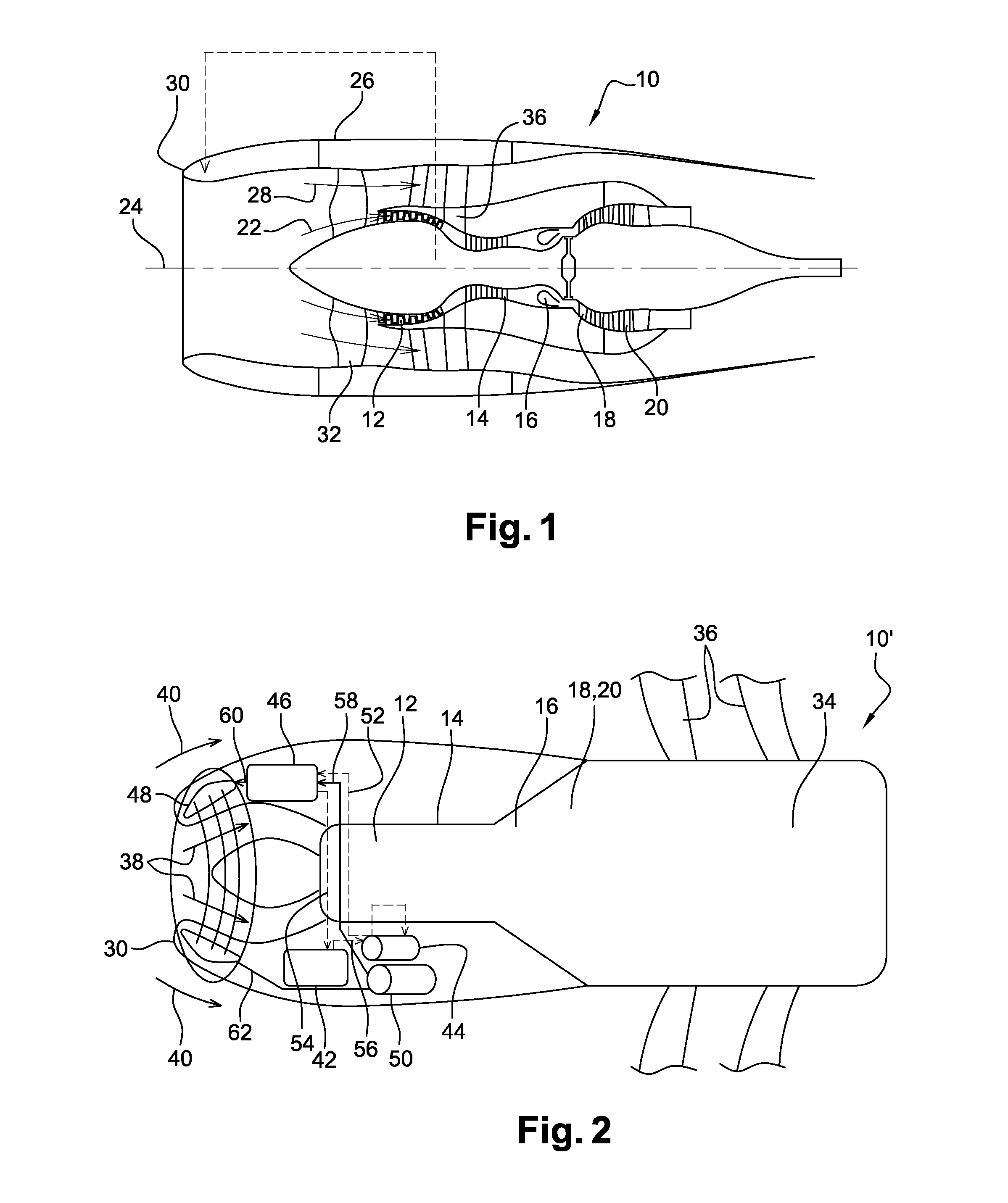
[0052]A propulsion assembly 10 comprises an engine or a turbine engine which is surrounded by a nacelle.

[0053]With reference to FIG. 1, the turbine engine is a bypass turbojet engine which comprises, from upstream to downstream in the direction of flow of the gases, a low-pressure compressor 12, a high-pressure compressor 14, a combustion chamber 16, a high-pressure turbine 18 and a low-pressure turbine 20, which define a stream of flow of a primary flow of gas 22.

[0054]The rotor of the high-pressure turbine 18 is rigidly connected to the rotor of the high-pressure compressor 14 so as to form a high-pressure body, whereas the rotor of the low-pressure turbine 20 is rigidly connected to the rotor of the low-pressure compressor 12 so as to form a low-pressure body. The rotor of each turbine rotates the rotor of the associated compressor about an axis 24 as a result of the thrust of the gases coming from the combustion chamber 16.

[0055]The nacelle 26 extends around the turbine engine a...


PUM


Abstract

Propulsion assembly, comprising a turbine engine surrounded by a nacelle comprising an annular air inlet lip, the propulsion assembly further comprising a circuit for lubricating elements of the turbine engine and a circuit for de-icing the air inlet lip, characterised in that said de-icing circuit comprises a heat exchanger comprising a primary circuit of oil supplied by said lubrication circuit and a secondary circuit of a heat transfer fluid for supplying at least one de-icing channel extending into said air inlet lip, said de-icing circuit further comprising a pump for circulating the heat transfer fluid into said at least one channel.

Description

TECHNICAL FIELD[0001]The present invention relates to a circuit for de-icing an air inlet lip of a propulsion assembly, in particular of an aircraft, and more precisely to a propulsion assembly comprising such a circuit.PRIOR ART[0002]The prior art comprises in particular FR-A1-2,987,602 and GB-A-2,314,887.[0003]A propulsion assembly comprises an engine of the turbine engine type which is surrounded by a nacelle, said nacelle comprising an annular air inlet lip in particular in the engine.[0004]When the turbine engine is a bypass turbojet engine, the air flow which passes into the air inlet lip passes through fan blading and then divides into a primary air flow which enters the turbine engine and a secondary air flow which flows around the turbine engine.[0005]When the turbine engine is a turboprop engine, for example of the open rotor pusher type (i.e. the pusher propellers of which are located downstream of the turbine engine, relative to the direction of flow of the air around sa...

Claims


Application Information

Patent Timeline
IPC IPC(8): B64D33/02F02C7/047
CPCB64D33/02B64D2033/0233F02C7/047Y02T50/60B64D15/02F02C7/14
Inventor LLAMAS CASTRO, NURIANGUYEN VAN, THOMAS JULIENMANUELA RAMOS, BRUNA
Owner SN DETUDE & DE CONSTR DE MOTEURS DAVIATION S N E C M A
Why Eureka
Try Eureka