
Two-dimensional/three-dimensional switchable display apparatus

a display apparatus and switchable technology, applied in the direction of electrical devices, instruments, optics, etc., can solve the problems of reduced luminance, reduced light luminance, and binocular disparity between the different images on the display panel, and achieve the effect of high luminan

Inactive Publication Date: 2016-04-28
SAMSUNG DISPLAY CO LTD
View PDF4 Cites 6 Cited by
  • Summary
  • Abstract
  • Description
  • Claims
  • Application Information

AI Technical Summary

Benefits of technology

This configuration enhances luminance, reduces manufacturing complexity and costs, and improves the quality of 3D images by minimizing color separation and moire phenomena, while also simplifying the display device's structure and reducing its thickness and weight.

Problems solved by technology

The parallax barrier separates left-eye images for the viewer's left eye from right-eye images for the viewer's right eye, and causes binocular disparity between the different images on the display panel.
Disadvantageously, however, these polarizers may reduce luminance of the light passing therethrough.
Therefore, the polarizers included in the liquid crystal lens are significant causes of luminance reduction.
However, when a polarization direction of the polarized light passing through the 2D display panel is inconsistent with a direction of a polarization axis of polarizers mounted on the liquid crystal lens, a λ / 2-phase difference film is required to match them with each other.
In addition, the polarizers are very expensive.
Therefore, a plurality of polarizers used for the 3D display device may increase the total price of the 3D display device to an undesirable degree.

Method used


Image

  • Two-dimensional/three-dimensional switchable display apparatus
  • Two-dimensional/three-dimensional switchable display apparatus
  • Two-dimensional/three-dimensional switchable display apparatus

Examples


Embodiment Construction

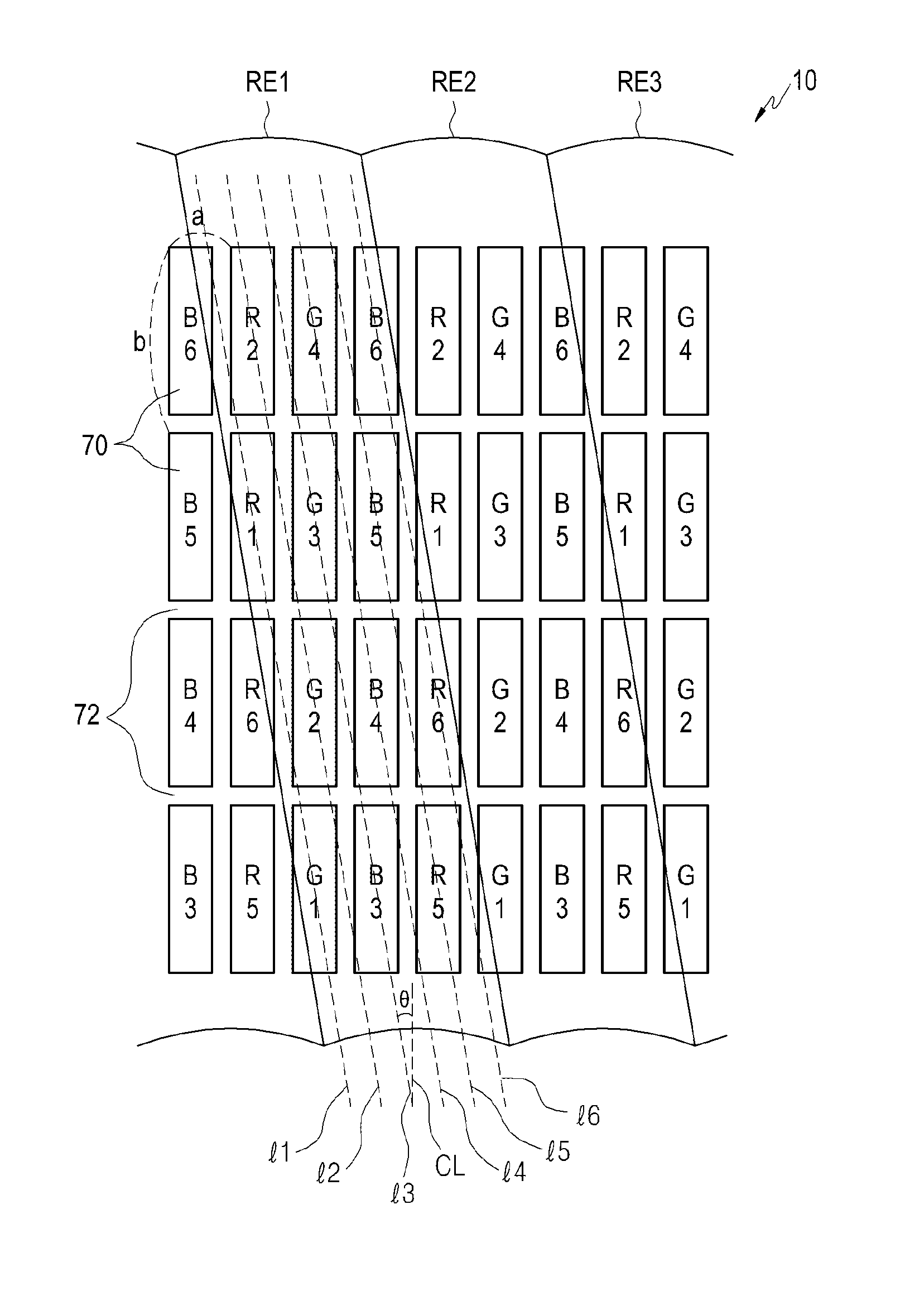
[0041]A 2D / 3D switchable display apparatus and a method for manufacturing a liquid crystal lens for the same according to an embodiment of the present invention will be described in detail below. Although many figures will be disclosed in this specification by way of example, it should be noted that these figures are not intended to limit the scope and sprit of the present invention unless defined in the appended claims. The same drawing reference numerals used in the specification and drawings will be understood to refer to the same elements, features and structures.

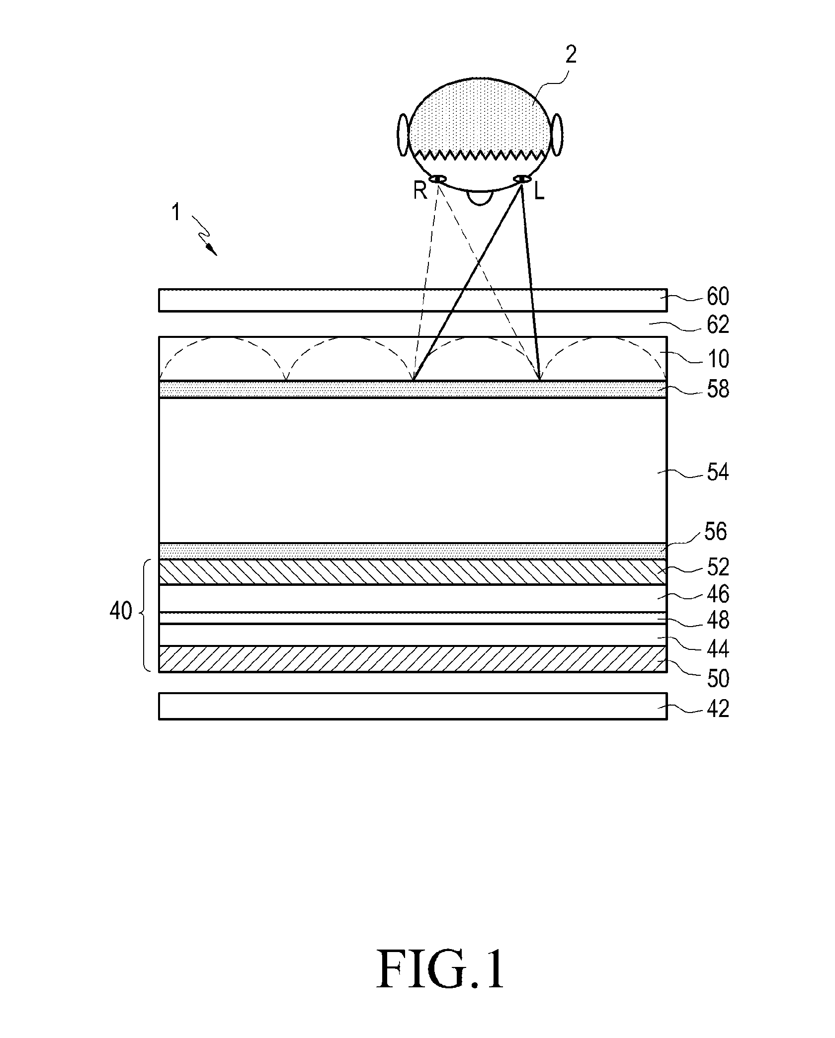
[0042]FIG. 1 is a cross-sectional view of a 2D / 3D switchable display apparatus according to an embodiment of the present invention.

[0043]Referring to FIG. 1, a 2D / 3D switchable display apparatus 1 includes a 2D liquid crystal display panel 40 and a liquid crystal lens 10 situated over the 2D liquid crystal display panel 40.

[0044]Although the 2D / 3D switchable display apparatus 1 having the 2D liquid crystal display panel...


PUM

PropertyMeasurementUnit
angle αaaaaaaaaaa
pre-tilt angle αaaaaaaaaaa
refractive indexaaaaaaaaaa

Abstract

A new 2D / 3D switchable display apparatus matches a polarization direction of light output from a 2D image display panel with a rubbing direction of a lower alignment layer of a liquid crystal lens, and tilts a rubbing direction of an upper alignment layer of the liquid crystal lens and a direction of a polarization axis of a polarizer at a predetermined angle, thereby reducing a loss of light passing through the liquid crystal lens, making it possible to improve luminance of images, improve the quality of 3D images in the horizontal direction, prevent or reduce color separation and moire phenomena, and reduce the manufacturing cost.

Description

PRIORITY[0001]This application is a divisional application of U.S. patent application Ser. No. 13 / 662,357 filed on Oct. 26, 2012, which claims the benefit under 35 U.S.C. §119(a) of the Korean Patent Application filed in the Korean Intellectual Property Office on Oct. 27, 2011 and assigned Serial No. 10-2011-0110489, the entire disclosure of which is hereby incorporated by reference.BACKGROUND OF THE INVENTION[0002]1. Field of the Invention[0003]Embodiments of the present invention relate generally to an apparatus for displaying three-dimensional (3D) images, and more particularly, to a two-dimensional / three-dimensional (2D / 3D) switchable autostereoscopic display apparatus.[0004]2. Description of the Related Art[0005]3D display technologies are classified into so-called stereoscopic display technology that requires viewers to wear special glasses such as liquid crystal shutter glasses to view 3D stereoscopic images, and so-called autostereoscopic display technology that does not req...

Claims


Application Information

Patent Timeline
Patent Type & Authority Applications(United States)
IPC IPC(8): G02B27/26G02B27/22G02F1/1343G02F1/1335G02F1/1337G02B30/25G02B30/28
CPCG02B27/26G02F1/133528G02F1/133784G02F2001/133531G02F1/134309G02F1/133526G02B27/2214G02F1/1337H04N13/305G02B30/25G02F1/133531G02B30/28G02F1/1335G02B30/27
Inventor YUN, HAE-YOUNGKIM, IL-JOOSEO, HYUN-SEUNGLEE, SEUNG-HOONKIM, JIN-HWANJEONG, SEUNG-JUN
Owner SAMSUNG DISPLAY CO LTD
Learn More