
Image display element holding mechanism, prism unit, and projector

a technology of image display element and holding mechanism, which is applied in the direction of optical elements, mountings, instruments, etc., can solve the problems of rising to displacement of pixels, achieve accurate and stable positional relationship between the prism and the image display element, prevent bending stress, and prevent the formation of cracks in the prism

Active Publication Date: 2016-04-28
KONICA MINOLTA INC
View PDF1 Cites 10 Cited by
  • Summary
  • Abstract
  • Description
  • Claims
  • Application Information

AI Technical Summary

Benefits of technology

This patent relates to a mechanism for holding an image display element in place, which prevents bending stress from negatively affecting the bond between the display element and the prism. This prevents cracks and degraded adhesion strength caused by the bending stress from the tightening of screws. By using this mechanism, the prism and display element can be positioned accurately and stably, resulting in high-quality image projections.

Problems solved by technology

In such projectors, an image display element and a prism are integrated with each other with an adhesive agent, but with the use of an adhesive agent, internal stress occurs mainly at an adhesion portion due to contraction force of the adhesive agent as it hardens, and the internal stress sometimes causes distortion of a member fixing the image display element, which may give rise to displacement of pixels.

Method used


Image

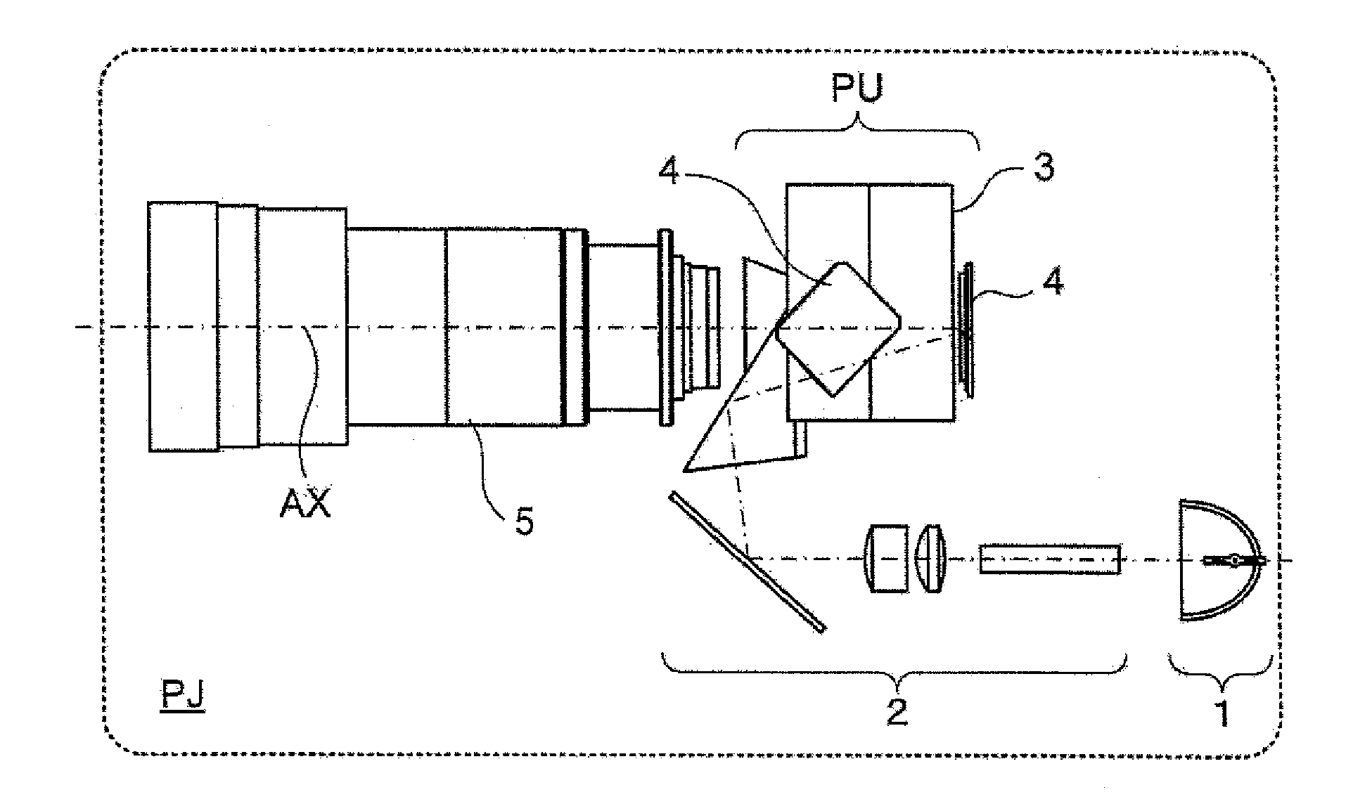
  • Image display element holding mechanism, prism unit, and projector
  • Image display element holding mechanism, prism unit, and projector
  • Image display element holding mechanism, prism unit, and projector

Examples


first embodiment

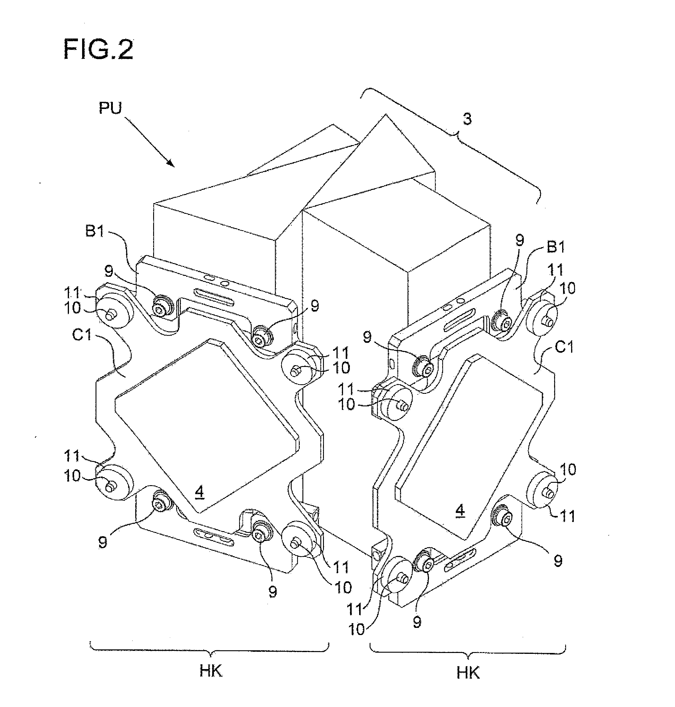
[0024]FIG. 3 is an exploded perspective view showing the prism unit having the image display element holding mechanism;

[0025]FIGS. 4A and 4B are sectional views schematically showing an image display element holding mechanism for comparison;

[0026]FIGS. 5A and 5B are sectional views schematically showing a first embodiment of the image display element holding mechanism;

second embodiment

[0027]FIGS. 6A and 6B are sectional views schematically showing the image display element holding mechanism;

third embodiment

[0028]FIGS. 7A and 7B are sectional views schematically showing the image display element holding mechanism;


PUM


Abstract

A holding mechanism for holding an image display element to a prism includes: a first fixing member fixed to the prism by an adhesive; and a second fixing member, which is fixed to the first fixing member using a screw, and which has the image display element directly or indirectly fixed to the second fixing member. A protruding section is provided at the periphery of a hole to be used for the purpose of fixing using the screw, and at the time of fixing the second fixing member to the first fixing member using the screw, the first fixing member and the second fixing member are directly or indirectly brought into contact with each other at the protruding section such that deformation due to screwing of the screw does not generate within a bonding region of the first fixing member.

Description

[0001]The present U.S. patent application is a U.S. National phase Application under 35 U.S.C. 371 of International Application PCT / JP2014 / 064075 filed on May 28, 2014. This application claims a priority under the Paris Convention of Japanese Patent Applications No. 2013-114125 filed on May 30, 2013, and No. 2013-119628 filed on Jun. 6, 2013, the entirety of each of which is incorporated herein by reference.TECHNICAL FIELD[0002]The present invention relates to an image display element holding mechanism, a prism unit, and a projector. The present invention more specifically relates to, for example, a holding mechanism for holding an image display element such as a liquid crystal panel, a digital micromirror device, or the like on a prism, a prism unit formed by integrating an image display element and a prism with each other with the holding mechanism, and a projector including the prism unit.BACKGROUND ART[0003]Recent years have been observing an increasingly more widespread use of ...

Claims


Application Information

Patent Timeline
Patent Type & Authority Applications(United States)
IPC IPC(8): G03B21/14G02B7/18
CPCG03B21/142G03B21/147G02B7/1805G02F1/133308G03B21/005G03B21/006G03B21/008G03B21/145G03B21/2066G03B33/06G03B33/12H04N9/3141H04N9/317
Inventor HAGA, DAISUKE
Owner KONICA MINOLTA INC
Learn More