Optical patterning mask and method for fabricating display device using the same

a technology of optical patterning and mask, which is applied in the direction of printing, layered products, and thermography, etc., can solve the problems of deteriorating affecting the performance affecting so as to prevent the damage reduce the deterioration of the transfer efficiency of the transfer material, and improve the effect of the light absorption layer

Inactive Publication Date: 2016-04-28
SAMSUNG DISPLAY CO LTD
View PDF3 Cites 3 Cited by
  • Summary
  • Abstract
  • Description
  • Claims
  • Application Information

AI Technical Summary

Benefits of technology

[0034]Since the optical patterning mask according to an embodiment of the present invention includes the protection layer that is formed on the light absorption layer that overlaps the opening of the reflective layer, an asher, for example, O2 gas, which is used to remove the residual transfer material of the transfer layer that remains on the bank layer after the transfer process using the optical patterning mask, can be prevented from coming in contact with and reacting on a part of the light absorption layer that is exposed from the optical patterning mask.
[0035]Through this, the light absorption layer can be prevented from reacting on the asher that is used to remove the residual transfer material of the transfer layer that remains on the bank layer. Accordingly, the light absorption layer can be prevented from being damaged, and the function of the light absorption layer can be prevented from deteriorating.
[0036]Further, in the case of reusing the optical patterning mask, from which the remaining transfer material of the transfer layer has been removed, deterioration of the transfer efficiency of the transfer material can be reduced.

Problems solved by technology

However, when cleaning the transfer material remaining on the optical patterning mask by injecting O2 gas energy, the light absorption layer may react on O2 gas and be damaged because it is exposed bare after the transfer material is transferred from the optical patterning mask.
Damaged light absorption layer may deteriorate the function of the light absorption layer that converts light into heat.
This may deteriorate the transfer efficiency of the transfer material.

Method used


Image

  • Optical patterning mask and method for fabricating display device using the same
  • Optical patterning mask and method for fabricating display device using the same
  • Optical patterning mask and method for fabricating display device using the same

Examples


Embodiment Construction

[0048]Advantages and features of the present invention and methods of accomplishing the same may be understood more readily by reference to the following detailed description of preferred embodiments and the accompanying drawings. The present invention may, however, be embodied in many different forms and should not be construed as being limited to the embodiments set forth herein. Rather, these embodiments are provided so that this disclosure will be thorough and complete and will fully convey the concept of the invention to those skilled in the art, and the present invention will only be defined by the appended claims.

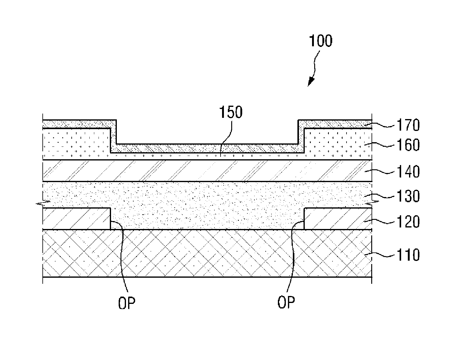
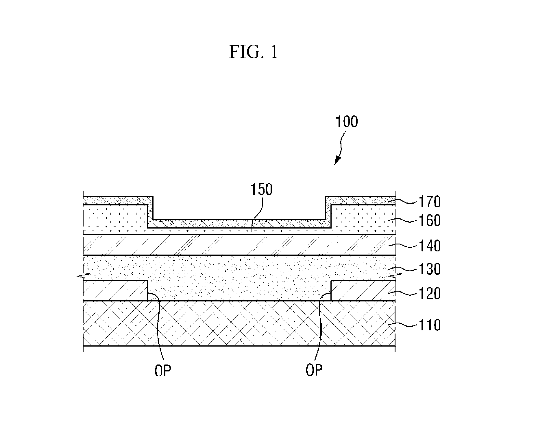
[0049]It will also be understood that when a layer is referred to as being “on” another layer or substrate, it can be directly on the other layer or substrate, or intervening layers may also be present. The same reference numbers indicate the same components throughout the specification.

[0050]It will be understood that, although the terms first, second, third etc. ma...


PUM

PropertyMeasurementUnit
thickaaaaaaaaaa
thickaaaaaaaaaa
thermal insulationaaaaaaaaaa

Abstract

The optical patterning mask had a protection layer on a light absorption layer. It prevents the light absorption layer from damaged by the cleaning gas when processing the used optical patterning mask for reuse. The protection layer may be made of the same material as bank layer or of material different from the bank layer. The bank layer defines the boundary of the area to be transferred in the transfer layer. The protection layer of the present invention can maintain longer the transfer efficiency of the optical patterning mask, even when the same mask is used repeatedly after cleaning, since the light absorption layer protected from cleaning process can maintain longer its heat conversion property.

Description

CROSS-REFERENCE TO RELATED APPLICATIONS[0001]This application claims priority from Korean Patent Application No. 10-2014-0146240, filed on Oct. 27, 2014 with the Korean Intellectual Property Office, the disclosure of which is incorporated herein in its entirety by reference.BACKGROUND[0002]1. Field[0003]The present invention relates to an optical patterning mask and a method for fabricating a display device using the same.[0004]2. Description of Background[0005]Among display devices, an organic light emitting display device is a self-luminous display device that has the advantages of wide viewing angle, superior contrast, and high response speed, and thus has been noticed as the next-generation display device.[0006]An organic light emitting display device has an organic light emitting layer that is made of an organic light emitting material disposed between an anode electrode and a cathode electrode. If an anode voltage and a cathode voltage are applied to these electrodes, respecti...

Claims


Application Information

Patent Timeline
Patent Type & Authority Applications(United States)
IPC IPC(8): H01L51/56H01L51/00
CPCH01L51/0013H01L51/56H10K71/18H10K71/00B41M5/40B41M5/46B41M5/426B41M5/42B41M5/48
Inventor CHOI, JIN BAEKLEE, YEON HWALEE, JOON GU
Owner SAMSUNG DISPLAY CO LTD
Why Eureka
Try Eureka