Electroacoustic converter
a technology of electroacoustic converter and acoustic converter, which is applied in the direction of electrical transducers, magnetic restriction transducers, earpiece/earphone attachments, etc., can solve the problems of difficult flexibly dealing with peak level adjustment in a specific frequency band, and sound waves cannot be generated with desired frequency characteristics, so as to achieve low pitch, achieve desired frequency characteristics easily, and lose any ease of operation
- Summary
- Abstract
- Description
- Claims
- Application Information
AI Technical Summary
Benefits of technology
Problems solved by technology
Method used
Image
Examples
first embodiment
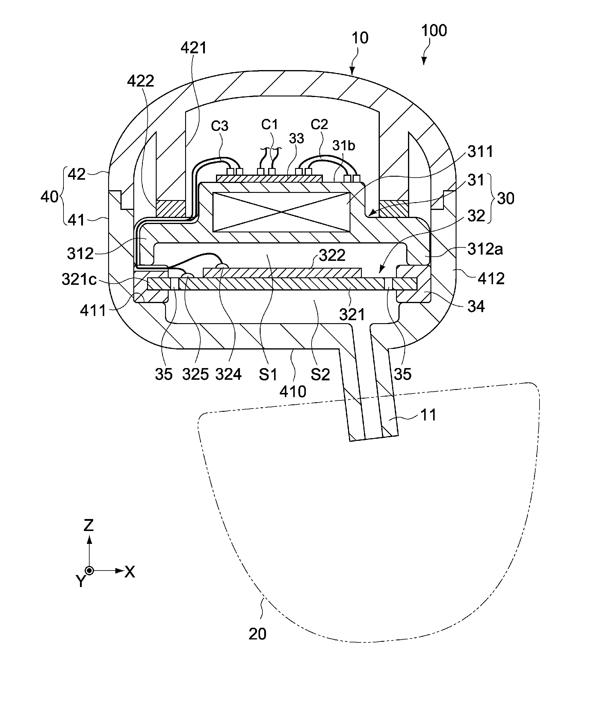
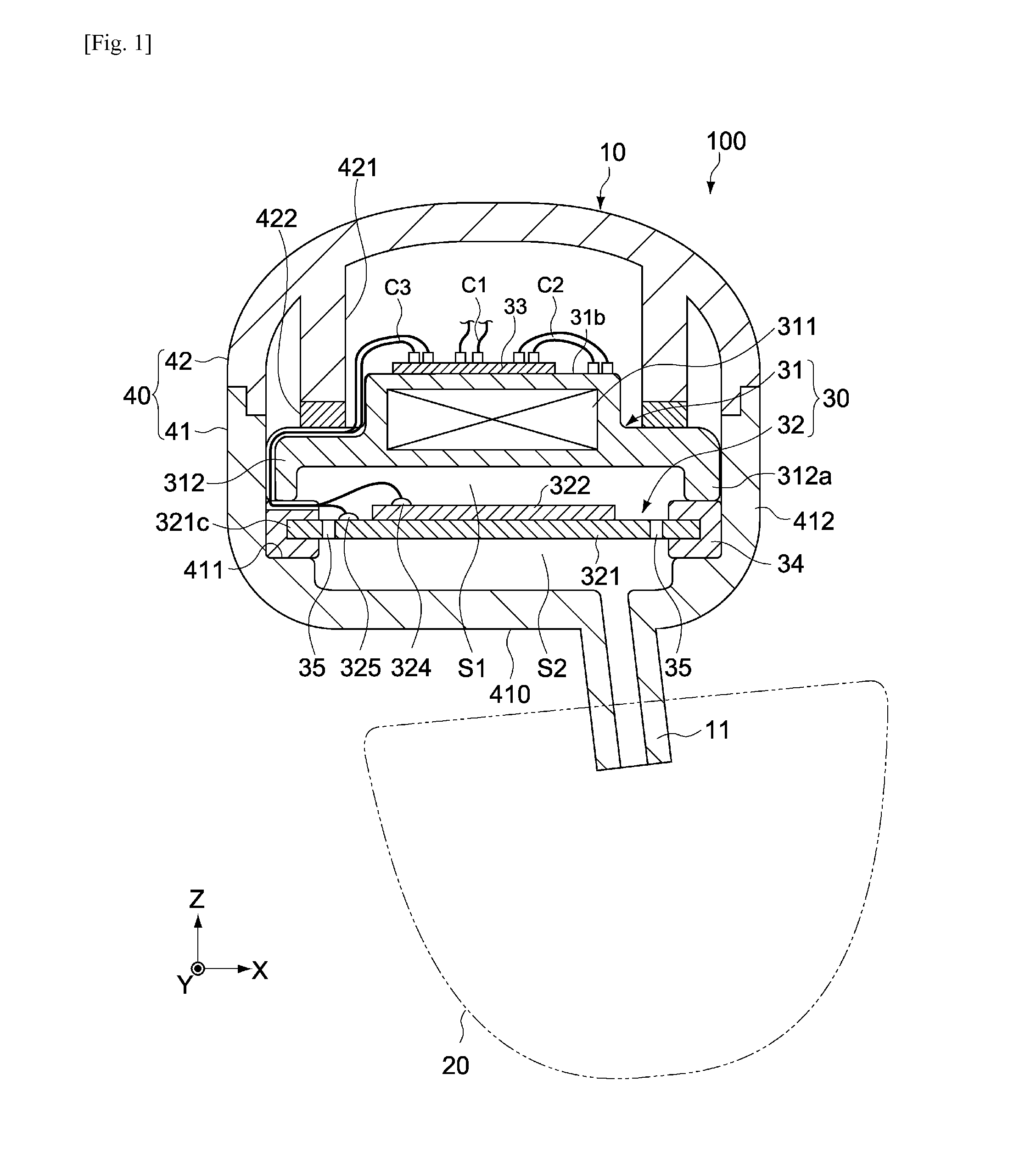
[0058]FIG. 1 is a schematic lateral section view showing the constitution of an earphone 100 as an electroacoustic converter pertaining to an embodiment of the present invention.
[0059]In the figure, the X-axis, Y-axis and Z-axis represent three axial directions crossing one another at right angles.
[0060]Overall Constitution of Earphone
[0061]The earphone 100 has an earphone body 10 and earpiece 20. The earpiece 20 is attached to a sound path 11 of the earphone body 10, while constituted in such a way that it can be worn in the user's ear.
[0062]The earphone body 10 has a sounding unit 30, and a housing 40 that houses the sounding unit 30.
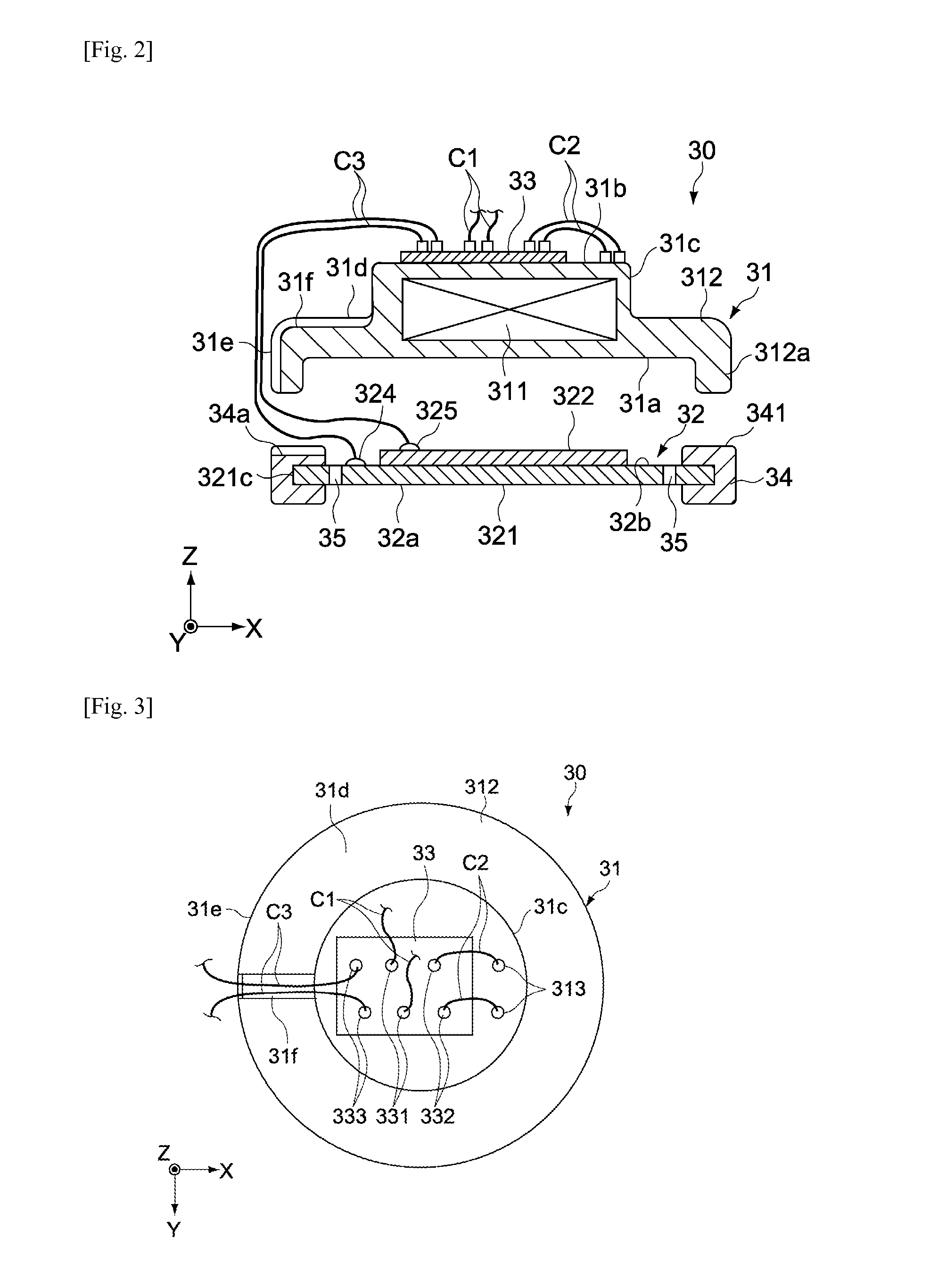
[0063]The sounding unit 30 has an electromagnetic sounding body 31 and piezoelectric sounding body 32. The housing 40 has an enclosure 41 and cover 42.
[0064]Enclosure
[0065]The enclosure 41 has the shape of a cylinder with a bottom and is typically constituted by injection-molded plastics. The enclosure 41 has an interior space in which the sounding un...
second embodiment
[0123]FIG. 12 is a schematic section view of an earphone 200 pertaining to another embodiment of the present invention. Constitutions different from those of the first embodiment are primarily explained below, and the same constitutions as in the aforementioned embodiment are not explained or explained briefly using the same symbols.
[0124]The earphone 200 of this embodiment is different from the aforementioned first embodiment in terms of the constitution of a sounding unit 50, especially that of a piezoelectric sounding body 52. The piezoelectric sounding body 52 has a vibration plate 521, and the piezoelectric element 322 joined to one principle surface (principle surface facing the first space Si in this example) of the vibration plate 521.
[0125]FIG. 13 is a schematic plan view showing the constitution of the piezoelectric sounding body 52. As shown in FIG. 13, multiple (three in the illustrated example) projecting pieces 521g that project radially outward in the diameter directi...
third embodiment
[0135]FIG. 20 is a schematic section view of an earphone 400 pertaining to another embodiment of the present invention. Constitutions different from those of the first embodiment are primarily explained below, and the same constitutions as in the aforementioned embodiment are not explained or explained briefly using the same symbols.
[0136]The earphone 400 of this embodiment is different from the aforementioned first embodiment in terms of the constitution of a sounding unit 70, especially that of a piezoelectric sounding body 72. The sounding unit 70 has an electromagnetic sounding body 31 and piezoelectric sounding body 72. The piezoelectric sounding body 72 is constituted in the same manner as the piezoelectric sounding body 32 in the first embodiment, except that the piezoelectric element 322 is joined to the second principle surface 32a of the vibration plate 321. The sounding unit 70 further has a ring-shaped member 54 placed between the support 411 of the enclosure 41 and the ...
PUM
 Abstract
Description
Claims
Application Information
 - R&D
- Intellectual Property
- Life Sciences
- Materials
- Tech Scout
- Unparalleled Data Quality
- Higher Quality Content
- 60% Fewer Hallucinations
Browse by: Latest US Patents, China's latest patents, Technical Efficacy Thesaurus, Application Domain, Technology Topic, Popular Technical Reports.
© 2025 PatSnap. All rights reserved.Legal|Privacy policy|Modern Slavery Act Transparency Statement|Sitemap|About US| Contact US: help@patsnap.com


