Heart Valve Repair and Replacement

a heart valve and valve body technology, applied in the field of heart valve repair and replacement, can solve the problems of poor surgical candidates, high morbidity and mortality, and impaired leaflet function, and achieve the effects of improving the surgical ability of many heart failure patients and improving the surgical ability of many patients

Active Publication Date: 2016-05-05
CARDIAC IMPLANTS
View PDF2 Cites 151 Cited by
  • Summary
  • Abstract
  • Description
  • Claims
  • Application Information

AI Technical Summary

Benefits of technology

[0036]Another aspect of the invention is directed to an apparatus for affixing a loop of material to tissue in a heart. This apparatus includes a housing that has an open front end. The housing has a cylindrical interior void that includes a first section and a second section, and the first section is located in front of the second section. This apparatus also includes an anchor disposed in the first section of the void. The anchor has a pointy front end and a back end, a first panel of material that has a cylindrically curved outer surface, a second panel of material that has a cylindrically curved outer surface, and a slot disposed between the first panel of material and the second panel of material that runs in a front-to-back direction. The front end of the anchor is configured for implantation into the tissue in a forward direction and the anchor is configured so that subsequent to implantation, the anchor resists extraction from the tissue in a backwards direction. This apparatus also includes a spring disposed in the second portion of the void in a compressed state, and an actuator configured to (a) prevent the spring from expanding from the compressed state prior to being actuated and (b) permit the spring to expand from the compressed state upon being actuated. The housing, the spring, the anchor, and the actuator are configured so that when the actuator is actuated, the spring expands into the first section and pushes the anchor forward such that at least a portion of the anchor exits the front end of housing, wherein the spring pushes the anchor with sufficient force to implant the anchor into the tissue.
[0037]In some embodiments, the housing has an opening in a sidewall and the actuator comprises a member that has a distal portion. The actuator is configured so that (a) prior to being actuated the distal portion of the member extends into the opening and prevents the spring from expanding from the compressed state and (b) upon being actuated the distal portion of the member is withdrawn from the opening, which permits the spring to expand from the compressed state.

Problems solved by technology

Such procedure is associated with high morbidity and mortality.
Leaflet function can be impaired as the result of prolapse of a leaflet due to ruptured chordae.
Due to the invasive nature of the mitral valve surgery, and the high risks involved in the procedure, many heart failure patients are poor surgical candidates.
Following the success of percutaneous replacement of the aortic valve, many attempts have been made to develop similar devices intended for percutaneous treatment of the mitral valve but due to the fact that this valve annulus is much bigger and amorphously shaped, and there are no lumen walls or calcific leaflets that may function as retaining surfaces like in the aortic valve, make it very difficult to prevent dislodgment of a valve expanded into place in the mitral position.

Method used


Image

  • Heart Valve Repair and Replacement
  • Heart Valve Repair and Replacement
  • Heart Valve Repair and Replacement

Examples


Embodiment Construction

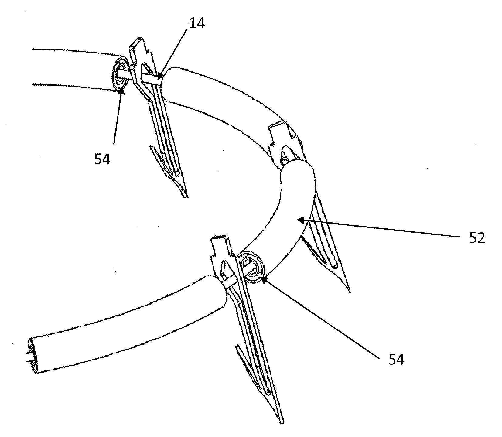
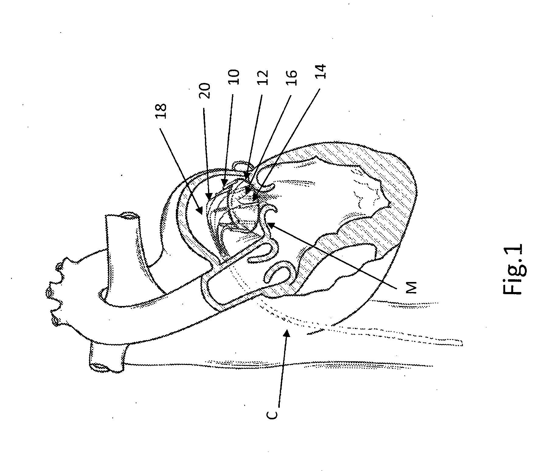
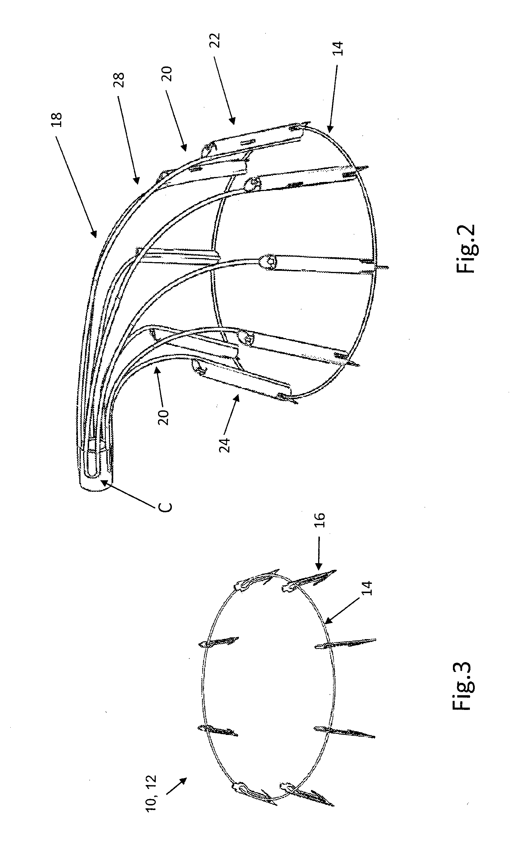
[0087]A heart valve repair device comprising an implant and delivery system is delivered into the heart in four sequential stages: In the first stage the implant and support scaffold are advanced in a collapsed configuration inside a capsule through the vascular system to the valve annulus (preferably the Mitral annulus but can be also the Tricuspid annulus). In the second stage after positioning the capsule close to the annulus a support scaffold is pushed outside of the capsule and the implant which is attached to the scaffold is spread into a round or D shape circumferential ring onto the valve annulus in 3 optional ways: 1) On the inflow side of the valve with attachment anchors pointing from the atrium side to the ventricle side; 2) On the inflow side of the valve with attachment anchors pointing from the ventricle side to the atrium side; and 3) On the outflow side of the valve with attachment anchors pointing from the ventricle side to the atrium side.

[0088]In the third stage...


PUM


Abstract

Apparatuses and methods are disclosed for performing a procedure on a heart valve in which a loop of material (160) is configured to contact at least a portion of the annulus or the leaflets of a valve. A plurality of anchors (16) are distributed about the loop and configured for implantation into the annulus or the leaflets in a forward direction. The anchors are configured to resist extraction in a backwards direction. A plurality of linking members (150) are affixed to the loop of material and at least a portion of each linking member passes through a slot (17) in a respective anchor so that the linking members can slide with respect to the slots. The anchors are then implanted into the annulus or the leaflets. The loop can then be used to retain a replacement valve or to cinch the annulus. A number of particularly advantageous anchor configurations are also disclosed.

Description

CROSS REFERENCE TO RELATED APPLICATIONS[0001]This Application claims the benefit of U.S. Provisional Application 61 / 831,632, filed Jun. 6, 2013, which is incorporated herein by reference.BACKGROUND[0002]The mitral valve is positioned in the heart left side, between the left atrium and the left ventricle. The most typical disease of the mitral valve is insufficiency or regurgitation which occurs when the valve leaflets do not coapt properly. Mitral valve repair by suturing a ring to reduce the annulus diameter is the procedure of choice to correct mitral regurgitation. With the use of current surgical techniques, most regurgitant mitral valves can be repaired or replaced with artificial valve prosthesis.[0003]In the past, mitral valve repair required an extremely invasive surgical approach that includes a sternotomy, cardio-pulmonary bypass, cardiac arrest, and an incision in the heart itself to expose the mitral valve. Such procedure is associated with high morbidity and mortality. ...

Claims


Application Information

Patent Timeline
Patent Type & Authority Applications(United States)
IPC IPC(8): A61F2/24
CPCA61F2/2442A61F2220/0008A61F2/2466A61F2/2445A61F2220/0016A61B17/0487A61B17/068A61B2017/00867A61B2017/0409A61B2017/0414A61B2017/0427A61B2017/0437A61B2017/0464A61B2017/0647
Inventor ALON, DAVID
Owner CARDIAC IMPLANTS
Why Eureka
Try Eureka