Devices and Methods for Dilating a Paranasal Sinus Opening and for Treating Sinusitis
a paranasal sinus and opening technology, applied in the field of paranasal sinus opening and sinusitis treatment, can solve the problems of increased microbial growth, increased microbial growth, and increased microbial growth, and achieve the effect of reducing oxygen tension and microbial growth
- Summary
- Abstract
- Description
- Claims
- Application Information
AI Technical Summary
Benefits of technology
Problems solved by technology
Method used
Image
Examples
example 1
[0123]An osmotic driver for a paranasal sinus dilator was made as follows. A tube of 304 stainless steel having an outside diameter of 0.64 mm (25 mils) and an inside diameter of 0.51 mm (20 mils) was cut to a length of 1.3 cm and de-burred. An extruded polymer tube (inner membrane) composed of Tecophilic HP-93A-100 polyurethane with an inside diameter slightly larger than that of the steel tube and having a wall thickness of 0.13 mm (5 mils) was slid over the steel tube and cut flush with the length of the steel tube. Next a distal osmotic tablet was fabricated according to the procedures described in Example 1 of U.S. Application Publication No. 2012 / 0053567, published Mar. 1, 2012, except as follows. First, Polyox 303 was sifted through a 100-mesh sieve. 8.5 g of minus 100 mesh material was transferred to a beaker. Sodium chloride powder was ground with a pestle in a mortar and sifted through a 100-mesh sieve. 15.0 g of sized sodium chloride was added to the Polyox. Next, Methoce...
example 2
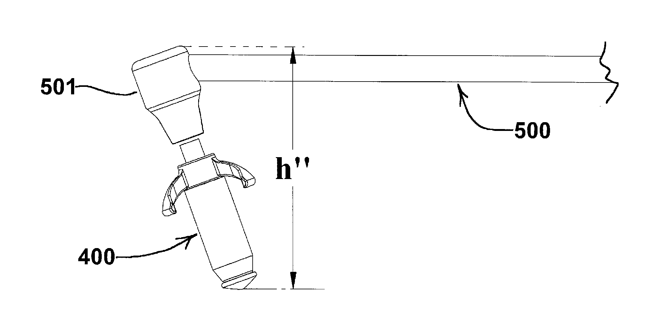
[0124]A maxillary sinus dilator was made as follows. Taking first an osmotic driver as described in Example 1, a proximal end piece having the same design and shape as end piece 107 shown in FIGS. 3, 4 and 5 was mounted on the proximal end of the driver. The end piece was comprised of injection molded acrylonitrile butadiene styrene having a pocket for the proximal end of the osmotic driver assembly to nest in, a through hole in the center of the pocket for the steel tube to go through, and an angled mounting arm having an angle θ of 110°, was slid over the proximal end of the thermally bonded assembly steel tube until it protruded through the end piece and the proximal end of the osmotic driver was nested inside the end piece pocket. The end piece was affixed to the osmotic driver using adhesive. The protruding steel tube was then mechanically flared against the end piece to create a mechanical stop. Next a stainless steel wire having a length of 1.2 cm (475 mils), a diameter of 0....
example 3
[0125]A sphenoid sinus dilator was made as follows. Taking first an osmotic driver as described in Example 1, a proximal end piece having the same design and shape as end piece 127 shown in FIGS. 6, 7 and 8 was mounted on the proximal end of the driver. The end piece was comprised of injection molded acrylonitrile butadiene styrene having a pocket for the proximal end of the osmotic driver assembly to nest in, a through hole in the center of the pocket for the steel tube to go through, and an angled mounting arm having an angle α of 15°, was slid over the proximal end of the thermally bonded assembly steel tube until it protruded through the end piece and the proximal end of the osmotic driver was nested inside the end piece pocket. The end piece was affixed to the osmotic driver using adhesive. The protruding steel tube was then mechanically flared against end piece to create a mechanical stop. Next a stainless steel wire having a length of 1.2 cm (475 mils), a diameter of 0.38 mm ...
PUM
 Abstract
Description
Claims
Application Information
 - R&D
- Intellectual Property
- Life Sciences
- Materials
- Tech Scout
- Unparalleled Data Quality
- Higher Quality Content
- 60% Fewer Hallucinations
Browse by: Latest US Patents, China's latest patents, Technical Efficacy Thesaurus, Application Domain, Technology Topic, Popular Technical Reports.
© 2025 PatSnap. All rights reserved.Legal|Privacy policy|Modern Slavery Act Transparency Statement|Sitemap|About US| Contact US: help@patsnap.com


