Impact Screwdriver

Active Publication Date: 2016-05-05
C & E FEIN
6 Cites 6 Cited by

AI-Extracted Technical Summary

Problems solved by technology

The known screwdriver is configured to tighten screw connections but does not have a measuring device in order to be able to set a predetermined tightening t...

Method used

[0065]The central controller is now programmed such that the measured intergral of contact durations Δt1, Δt2, Δt3 . . . between the hammer 14 and anvil 18 is compared with a stored dependence of the torque on the impulse duration and is taken into consideration in a calculation of the tightening torque. Since the rotational speed n is measured by the central controller 22 via an associated s...

Benefits of technology

[0006]In view of this it is an object of the invention to disclose an impact screwdriver which allows...

Abstract

An impact screwdriver having a housing is disclosed comprising an impact mechanism including a hammer interacting with an anvil for driving a tool, wherein the hammer is arranged on a drive shaft so as to be axially movable and preloaded in the axial direction, and wherein the hammer is driven by the drive shaft via a driver and is preloaded counter to the force of a spring element in order to trip and to transmit a rotary impulse to the anvil when a particular rotation angle is exceeded, wherein the hammer and the anvil are mounted in a manner electrically insulated from one another and are connected to a voltage source, and wherein a sensor is provided for monitoring a current flow between the hammer and anvil during contact thereof for determining a contact duration between the hammer and the anvil.

Application Domain

Derricks/mastsSpanners +4

Technology Topic

ElectricityVoltage source +2

Image

  • Impact Screwdriver
  • Impact Screwdriver
  • Impact Screwdriver

Examples

  • Experimental program(1)

Example

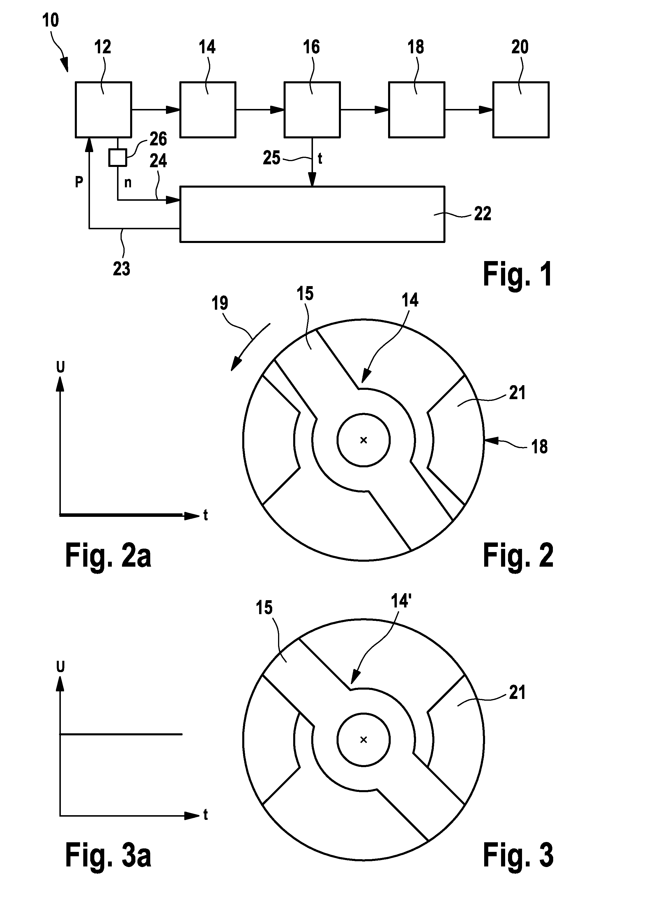
[0046]FIG. 1 shows a simplified circuit diagram of an impact screwdriver according to the invention, which is designated as a whole by the numeral 10.
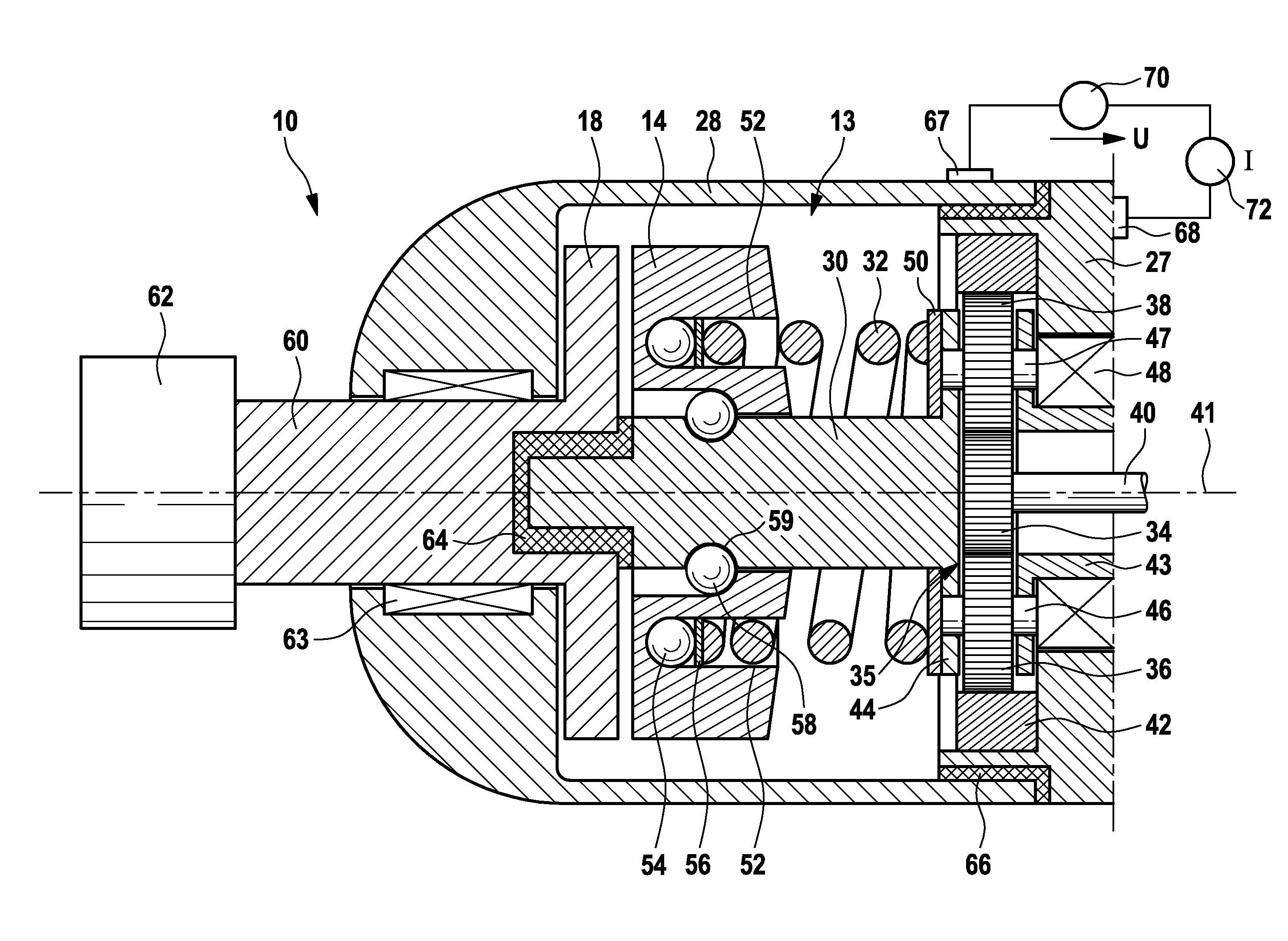
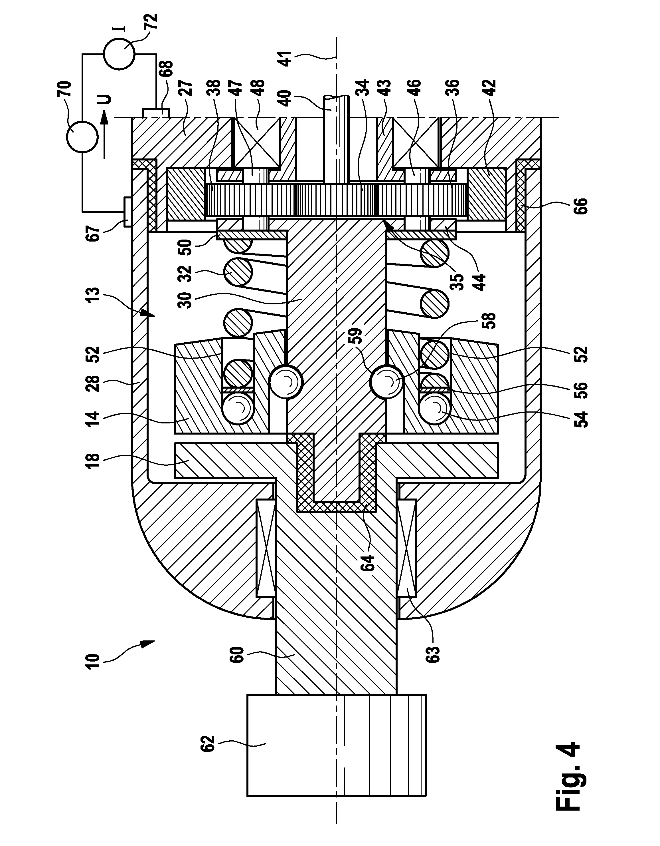
[0047]The impact screwdriver has a drive 12, for instance in the form of an electric motor which is coupled to a gear mechanism. The drive 12 drives a movably arranged hammer 14 which interacts with an anvil 18 in order to transmit a sequence of rotary impulses to the latter. Via an electric coupling 16 between the hammer 14 and anvil 18 the respective contact duration t between the hammer 14 and anvil 18 is determined and transmitted via a line 25 to a central controller 22. The anvil 18 is coupled to an output shaft 20 on which a tool such as a bit or a nut for tightening a screw connection is accommodated.
[0048]The central controller 22, which is preferably embodied as a microprocessor controller, controls the output P of the drive 12 via a line 23. Via an associated line 24, the rotational speed n of the drive 12 is sensed by the central controller 22 by means of a sensor 26.
[0049]For the measurement, an electrical contact duration between the hammer 14 and anvil 18, as indicated at 16, is determined and evaluated by the central controller 22.
[0050]FIG. 2 schematically illustrates how the hammer 14 is located in a position away from the anvil 18 such that there is no electrical contact, as is indicated schematically in FIG. 2a. By way of a rotary impulse on the hammer 14 in the direction of the arrow 19 as per FIG. 2, the hammer 14 moves from the position illustrated in FIG. 2 into a position shown in FIG. 3, which is indicated by 14′. In this case, the hammer 14 transmits its rotational energy via its two drivers 15 in part to associated protrusions 21 on the anvil 18. As a result of the direct contact between the hammer and anvil, a voltage signal, which is schematically illustrated in FIG. 3a, occurs during the contact.
[0051]The structure of the impact screwdriver 10 will now be explained in more detail with reference to FIG. 4.
[0052]The impact screwdriver 10 has a first housing part 27, which is illustrated only in part in FIG. 4 and in which a motor (only motor shaft 40 indicated) in addition to an associated gear mechanism 35 and an impact mechanism 13 are held. The first housing part 27 is connected via an electrically isolating connection 66 to a second housing part 28 into which the impact mechanism 13 projects and in which an anvil 18, which is provided at the end of an output shaft 60, is accommodated by means of a bearing 63. Provided at the outer end of the output shaft 60 is a tool receptacle 62 in which a screwdriving tool, for instance a bit or a nut, can be inserted in order to tighten a screw connection.
[0053]The gear mechanism 35 is configured as a planetary gear and has a planet gear carrier 43 which is mounted in a rotatable manner on the first housing part 27 by means of a bearing 48. On the planet gear carrier 43, a total of three planet wheels 36, 38, of which only two are discernible in FIG. 4, are mounted in a rotatable manner on shaft stubs 46, 47 which are connected to an associated flange extension 44 of a drive shaft 30. The drive shaft 30 is mounted via an electrically isolating plain bearing 64 in a recess in the anvil 18 and is mounted on the gear-mechanism side on the first housing part 27 via the planet wheel carrier 43 by means of the bearing 48.
[0054]The planetary gear 35 is driven via the motor shaft 40, at the end of which provision is made of a sun gear 34 which meshes with the planet gears 36, 38. Externally, the planet gears 36, 38 engage in a stationary ring gear 42 which is accommodated on the second housing part 27. If the motor shaft 40 is driven, the sun gear 34 drives the planet gears 36, 38 and causes the planet gear carrier 43 to rotate about a longitudinal axis 41 of the motor shaft 40 and the drive shaft 30, respectively.
[0055]On the drive shaft 30, the hammer 14 is arranged in an axially displaceable manner and is preloaded in the direction of the anvil 18 by means of a coil spring 32 which is supported on the flange extension 44 via a ring 50. The coil spring 32 engages with its end in an annular recess 52 in the hammer 14 and is supported via a disc 56 on balls 54 which bear against the end of the annular recess 52.
[0056]The hammer 14 is mounted in an axially displaceable manner by means of two balls 58 which protrude partially outwards from the surface of the drive shaft 30. The balls 58 interact with a curved track 59 which extends in a spiral shape along the outer surface of the drive shaft. In principle, one ball 58, which interacts with a curved track 59, would suffice. In the exemplary embodiment illustrated, however, provision is made of two curved tracks 59 which are offset through 180° with respect to one another and interact in this case with in each case one ball 58.
[0057]With the aid of this arrangement, when a relatively large torque is exerted as a particular limit counter-torque on the drive shaft 30 by the screw connection, the hammer 14 carries out an axial movement, counter to the spring force of the coil spring 32, in the direction of the gear mechanism 35 with a superimposed rotary movement relative to the drive shaft 30. The hammer 14 thus rotates along the curved track 59 and trips when a particular rotation angle is exceeded and is moved in the direction of the anvil 18 again under the action of the spring force, such that the drivers 15 of the hammer 14 come into contact with the associated protrusions 21 on the anvil 18 and the hammer 14 transmits its rotary impulse to the anvil 18, as is illustrated in FIG. 3. During the rotary drive by the hammer 14, mechanical and electrical contact occurs between the hammer 14 and anvil 18.
[0058]The hammer 14 is connected to the first housing part 27 in an electrically conductive manner via its bearing on the drive shaft 30 and the planetary gear set 35.
[0059]In a corresponding manner, the anvil 18 is connected to the second housing part 28 in an electrically conductive manner via the output shaft 60 and the bearing 63.
[0060]Since a voltage source 70 is connected between the first housing part 27 and the second housing part 28 via associated contacts 67, 68, contact making between the hammer 14 and anvil 18 can be monitored by means of a sensor 72 arranged between said housing parts.
[0061]As long as the hammer 14 is in mechanical contact with the anvil 18 and thus a rotary impulse is transmitted to the anvil 18, this is registered by a corresponding signal from the sensor 72 (cf. FIG. 3a) which is transmitted to the central controller 22 via the line 25.
[0062]A sequence of impact impulses thus occurs, as is illustrated schematically in FIG. 5.
[0063]The impulse duration decreases from impulse to impulse, i.e. Δt1 is greater than the impulse duration Δt2 of the following impulse, which is in turn greater than the impulse duration of the next impulse Δt3.
[0064]Initially, a relatively small torque transmission and a relatively long impulse duration occur. During the following impulses, the impulse duration decreases and the transmitted torque increases, as is indicated in the top half of FIG. 5. The impulse duration is sensed by way of the electrical contact making, as described above.
[0065]The central controller is now programmed such that the measured intergral of contact durations Δt1, Δt2, Δt3. . . between the hammer 14 and anvil 18 is compared with a stored dependence of the torque on the impulse duration and is taken into consideration in a calculation of the tightening torque. Since the rotational speed n is measured by the central controller 22 via an associated sensor (not illustrated) or optionally the output P is known via the controller, the central controller 22 can determine the tightening torque of the screw connection with great accuracy from the measured impulse sequence of the contact durations Δt1, Δt2, Δt3. . . Preferably the central controller 22 is configured for switching off the drive when a predetermined tightening torque is reached.

PUM

no PUM

Description & Claims & Application Information

We can also present the details of the Description, Claims and Application information to help users get a comprehensive understanding of the technical details of the patent, such as background art, summary of invention, brief description of drawings, description of embodiments, and other original content. On the other hand, users can also determine the specific scope of protection of the technology through the list of claims; as well as understand the changes in the life cycle of the technology with the presentation of the patent timeline. Login to view more.

Similar technology patents

Shaft of a gas-turbine engine, in particular a radial shaft or a shaft arranged at an angle to the machine axis

InactiveUS9217463B2simply designeasy and cost-effective
Owner:ROLLS ROYCE DEUT LTD & CO KG

Optical combiner device

ActiveUS20050175347A1cost-effectiveminimize loss
Owner:OMRON MANAGEMENT CENT OF AMERICA

Rainwater collection apparatus and pumping system

InactiveUS7025879B1promote conservation of watereasy and cost-effective
Owner:TICKNOR MARTIN F

Imposed current motor drive

Owner:DIALOG SEMICONDUCTOR

Structure of button for electronic product

InactiveUS6861603B1cost-effectiveeliminate jamming
Owner:PATEN WIRELESS TECH

Versatile system for charge dissipation in the formation of semiconductor device structures

ActiveUS20060033173A1simple yet effectiveeasy and cost-effective
Owner:TEXAS INSTR INC

Magnetically operated driving tool

InactiveUS6955282B1easy to useeasy and cost-effective
Owner:KIMPLE DAVID W

Classification and recommendation of technical efficacy words

  • cost-effective
  • easy and cost-effective

Nano graphene platelet-based conductive inks

InactiveUS20100000441A1cost-effectivelow viscosity
Owner:GLOBAL GRAPHENE GRP INC

Button anchor system for moving tissue

InactiveUS20060064125A1simple and easy to usecost-effective
Owner:CANICA DESIGN

Data stream filtering apparatus & method

InactiveUS20020146026A1cost-effectivesimple and low cost
Owner:RPX CLEARINGHOUSE

Rainwater collection apparatus and pumping system

InactiveUS7025879B1promote conservation of watereasy and cost-effective
Owner:TICKNOR MARTIN F

Shaft of a gas-turbine engine, in particular a radial shaft or a shaft arranged at an angle to the machine axis

InactiveUS9217463B2simply designeasy and cost-effective
Owner:ROLLS ROYCE DEUT LTD & CO KG

Versatile system for charge dissipation in the formation of semiconductor device structures

ActiveUS20060033173A1simple yet effectiveeasy and cost-effective
Owner:TEXAS INSTR INC

Magnetically operated driving tool

InactiveUS6955282B1easy to useeasy and cost-effective
Owner:KIMPLE DAVID W
Why Eureka
Try Eureka